AIR CONDITIONING
A/C Wiring Diagram for Mercury Tracer LS 1997

List of elements for A/C Wiring Diagram for Mercury Tracer LS 1997:
- (behind top of (main harn, left cowl panel) near rear window def sw breakout)
- (dashpanel to headlamp harn, near multi- function switch breakout)
- (engine harn, near brake fluid level switch breakout)
- A/c
- A/c clutch field coil
- A/c low pressure switch (right rear of engine compartment, on accumulator)
- A/c on indi- cator
- A/c switch
- A/c wac relay
- A/c-
- Blower circuit breaker 30a
- Blower motor
- Blower motor relay (left side of i/p)
- Blower motor resistor (behind right side of i/p, in a/c plenum)
- Blower switch
- Breakout)
- C110
- C133
- C138
- C147
- C200
- C220
- C240
- C272
- C273
- Constant control relay module (ccrm) (left front of engine)
- Controls system
- Cooling fan fusible link 40a
- Defrost
- Electric cooling fan
- Engine
- Engine compartment fuse box
- Engine fuse 15a
- Floor flr/def
- Fuel injector fusible link 30a
- Fuel pump relay
- G110 (left front of engine)
- G115 (lower rear of engine)
- G200
- G201 (behind right side of i/p)
- Heater control assembly (integrated control panel) (icp)
- Hfc relay
- Hot at all times
- Hot in run
- Hot in start or run
- I/p fuse panel
- J/c 3
- J/c 6
- Lfc relay
- Lfc relay control
- Max a/c
- Off
- Panel
- Panel floor
- Pcm power relay
- Powertrain control module (pcm) (behind center of i/p)
- Rear wiper fuse 10a
- Red
- S104 (eng harn, near eng compt fuse box breakout)
- S106 (eng harn, near egr vacuum regulator breakout)
- S116 (eng harn, near electric cooling fan breakout)
- S120
- S213
- S234 (dashpanel to headlamp harn, behind left side of i/p)
- Solid state
- Wiper fuse 20a
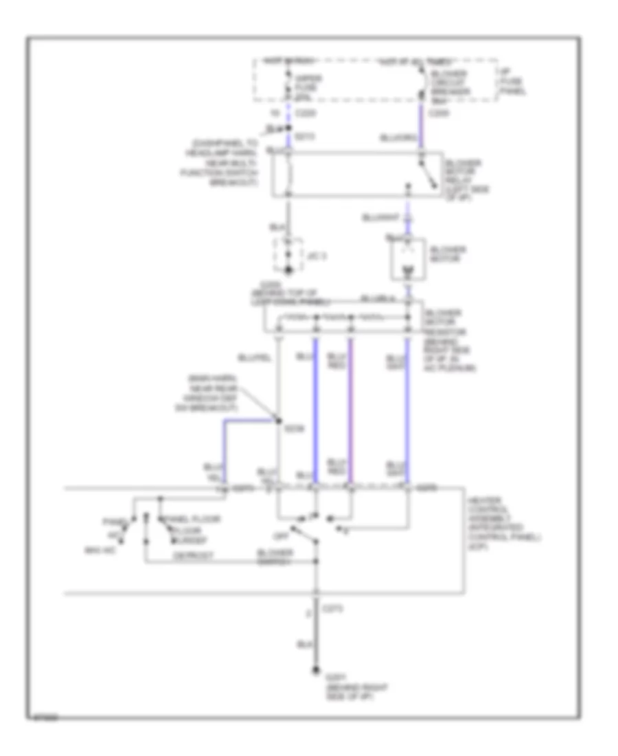
Heater Wiring Diagram for Mercury Tracer LS 1997
List of elements for Heater Wiring Diagram for Mercury Tracer LS 1997:
- (behind top of left cowl panel)
- (dashpanel to headlamp harn, near multi- function switch breakout)
- (main harn, near rear window def sw breakout)
- A/c
- Blower circuit breaker 30a
- Blower motor
- Blower motor relay (left side of i/p)
- Blower motor resistor (behind right side of i/p, in a/c plenum)
- Blower switch
- C200
- C220
- C272
- C273
- Defrost
- Floor flr/def
- G200
- G201 (behind right side of i/p)
- Heater control assembly (integrated control panel) (icp)
- Hot at all times
- Hot in run
- I/p fuse panel
- J/c 3
- Max a/c
- Off
- Panel
- Panel floor
- S213
- S238
- Wiper fuse 20a