AIR CONDITIONING
A/C Wiring Diagram for Mercury Villager GS 1995

List of elements for A/C Wiring Diagram for Mercury Villager GS 1995:
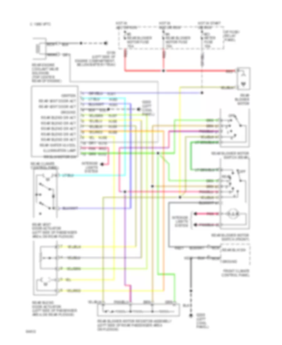
Rear A/C Wiring Diagram for Mercury Villager GS 1995
List of elements for Rear A/C Wiring Diagram for Mercury Villager GS 1995: