AIR CONDITIONING
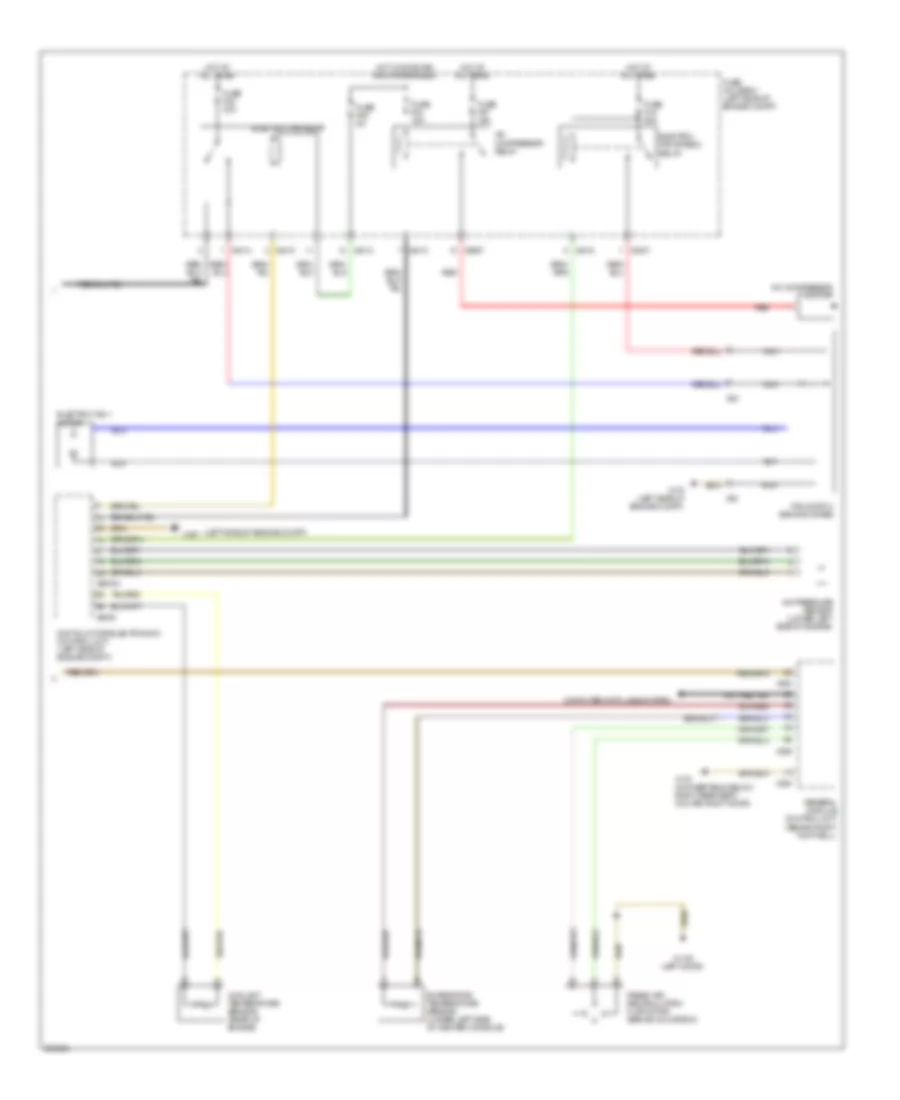
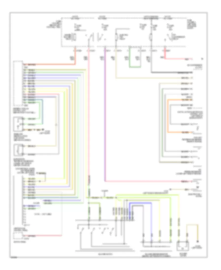
Automatic A/C Wiring Diagram, with Dual Stage Cooling Fans (1 of 2) for MINI Cooper 2007

List of elements for Automatic A/C Wiring Diagram, with Dual Stage Cooling Fans (1 of 2) for MINI Cooper 2007:
- (left door)
- Air distribution motor (center console)
- Air stratification flap motor (under right side of dash center console)
- Blower motor
- Blower output stage (center of dash)
- Computer data lines system
- Fuse f30 5a
- Fuse f31 30a
- Fuse f41 5a
- Fuse holder 2 (behind left footwell trim)
- Heat exchanger sensor (behind center of dash)
- Heater blower relay
- Heating & a/c control module
- Hot at all times
- Hot in accy, run and start
- Hot in on or start
- Interior temperature sensor
- Nca
- Power steering control module fan
- Red
- Solar sensor (top of dash)
- Steering control module fan relay (left side of left footwell)
- Switch panel
- X10201
- X10205
- X10207
- X1108
- X1108 (left door)
- X13230 (under left rear seat) (convertible) (left door) (coupe)
- X1879
- X610
- X6454
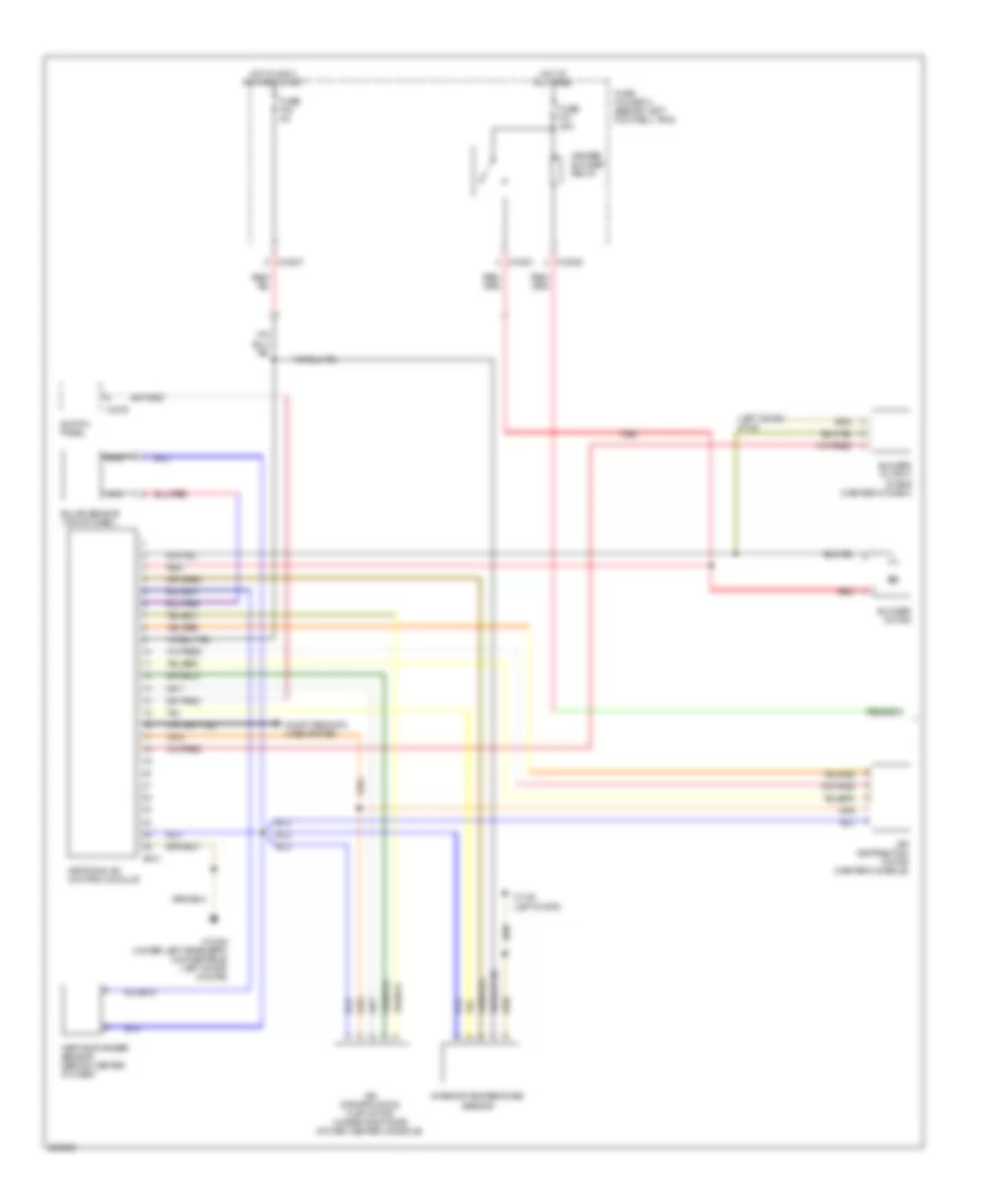
Automatic A/C Wiring Diagram, with Dual Stage Cooling Fans (2 of 2) for MINI Cooper 2007
List of elements for Automatic A/C Wiring Diagram, with Dual Stage Cooling Fans (2 of 2) for MINI Cooper 2007:
- (left side of engine compt)
- A/c compressor clutch
- A/c compressor relay
- A/c pressure sensor (lower left side of engine)
- Computer data lines system
- Coolant temperature sensor (rear of engine)
- Digital motor electronics control unit (left side of engine compt)
- Electric fan 1 motor
- Electric fan relay
- Electric fan stage 2 relay
- Evaporator temperature sensor (under left side of center console)
- Fan switch second stage
- Fresh air/ recirculation flap motor (behind glove box)
- Fuse f03 15a
- Fuse f05 5a
- Fuse f07 30a
- Fuse f08 30a
- Fuse fl9 50a
- Fuse holder 3 (left side of engine compt)
- General module control unit (behind right footwell)
- Hot at all times
- Hot w/ dme main relay energized
- Nca
- Red
- X1108 (left door)
- X167
- X175 (left side of engine compt)
- X179 (convertible: below right rear seat) (coupe: right door)
- X253
- X254
- X255
- X4007
- X4010
- X4013
- X4014
- X53
- X6000
- X60004
- X8687
Automatic A/C Wiring Diagram, with Single Stage Cooling Fans (1 of 2) for MINI Cooper 2007
List of elements for Automatic A/C Wiring Diagram, with Single Stage Cooling Fans (1 of 2) for MINI Cooper 2007:
- (left door) x1108
- Air distribution motor (center console)
- Air stratification flap motor (under right side of dash center console)
- Blower motor
- Blower output stage (center of dash)
- Computer data lines system
- Fuse f30 5a
- Fuse f31 30a
- Fuse holder 2 (behind left footwell trim)
- Heat exchanger sensor (behind center of dash)
- Heater blower relay
- Heating & a/c control module
- Hot at all times
- Hot in accy, run and start
- Interior temperature sensor
- Nca
- Red
- Solar sensor (top of dash)
- Switch panel
- X10201
- X10205
- X10207
- X1108 (left door)
- X13230 (under left rear seat) (convertible) (left door) (coupe)
- X1879
- X610
Automatic A/C Wiring Diagram, with Single Stage Cooling Fans (2 of 2) for MINI Cooper 2007
List of elements for Automatic A/C Wiring Diagram, with Single Stage Cooling Fans (2 of 2) for MINI Cooper 2007:
- (left side of engine compt)
- A/c compressor clutch
- A/c compressor relay
- A/c pressure sensor (lower left side of engine)
- Computer data lines system
- Coolant temperature sensor (rear of engine)
- Digital motor electronics control unit (left side of engine compt)
- Electric fan 1 motor
- Electric fan relay
- Evaporator temperature sensor (under left side of center console)
- Fresh air/ recirculation flap motor (behind glove box)
- Fuse f03 15a
- Fuse f05 5a
- Fuse f07 30a
- Fuse f08 20a
- Fuse holder 3 (left side of engine compt)
- General module control unit (behind right footwell)
- Hot at all times
- Hot w/ dme main relay energized
- Red
- X1108 (left door)
- X167
- X175 (left side of engine compt)
- X179 (convertible: below right rear seat) (coupe: right door)
- X253
- X254
- X255
- X4010
- X4013
- X4014
- X6000
- X60004
- X8687
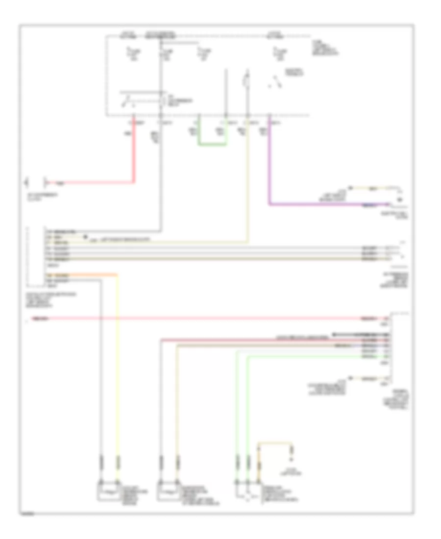
Manual A/C Wiring Diagram, with Dual Stage Cooling Fans for MINI Cooper 2007
List of elements for Manual A/C Wiring Diagram, with Dual Stage Cooling Fans for MINI Cooper 2007:
- (convertible: under left rear seat) (coupe: left door) x13230
- (left door)
- (not used)
- (or red)
- A/c compres- sor relay
- A/c compressor clutch
- A/c pressure sensor (lower left side of engine)
- Blower motor
- Blower series resistor (below left side of glove box)
- Blower switch
- Coolant temperature sensor (rear of engine)
- Digital motor electronics control unit (left side of engine compt)
- Elec- tric fan stage relay
- Electric fan 1 motor
- Electric fan relay
- Evaporator temperature sensor (under left side of center console)
- Fresh air/ recirculation flap motor (behind glove box)
- Fuse f03 15a
- Fuse f05 5a
- Fuse f07 30a
- Fuse f08 30a
- Fuse f31 30a
- Fuse f41 5a
- Fuse fl9 50a
- Fuse holder 2 (behind left footwell trim)
- Fuse holder 3 (left side of engine compt)
- General module control unit (behind right footwell)
- Heater blower relay
- Heating & a/c control panel
- Hot at all times
- Hot in on or start
- Hot w/ dme main relay energized
- Nca
- Power steering control module fan
- Red
- Second stage fan switch
- Steering control module fan relay (left side of left footwell)
- Switch panel
- W/ ihkr
- W/ ihs
- X01117
- X10201
- X10205
- X10207
- X1108
- X1108 (left door)
- X175 (left side of engine comp)
- X1879
- X253
- X255
- X4007
- X4010
- X4013
- X4014
- X53
- X6000
- X60004
- X6454
- X8687
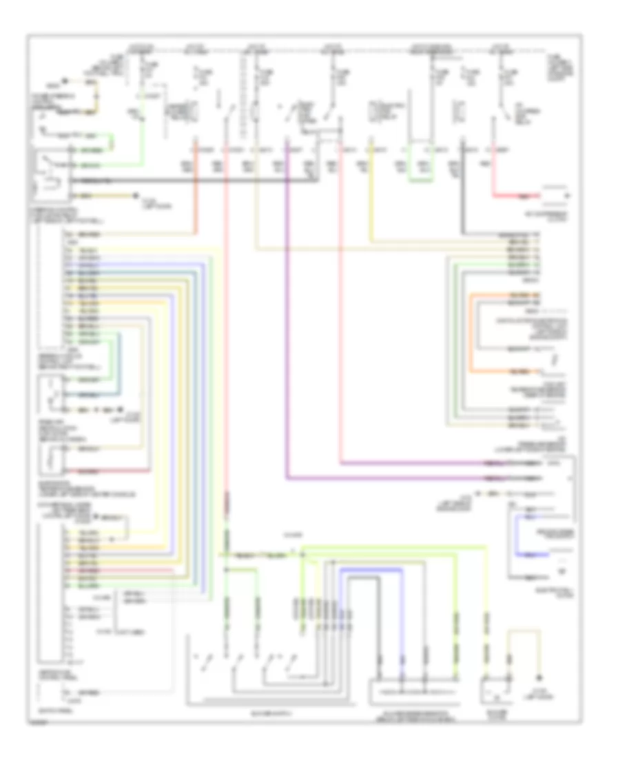
Manual A/C Wiring Diagram, with Single Stage Cooling Fans for MINI Cooper 2007
List of elements for Manual A/C Wiring Diagram, with Single Stage Cooling Fans for MINI Cooper 2007:
- (convertible: under left rear seat) (coupe: left door) x13230
- (left door)
- (not used)
- (or red)
- A/c compressor clutch
- A/c compressor relay
- A/c pressure sensor (lower left side of engine)
- Blower motor
- Blower series resistor (behind left side of glove box)
- Blower switch
- Coolant temperature sensor (rear of engine)
- Digital motor electronics control unit (left side of engine compt)
- Electric fan 1 motor
- Electric fan relay
- Evaporator temperature sensor (under left side of center console)
- Fresh air/ recirculation flap motor (behind glove box)
- Fuse f03 15a
- Fuse f05 5a
- Fuse f07 30a
- Fuse f08 20a
- Fuse f31 30a
- Fuse holder 2 (behind left footwell trim)
- Fuse holder 3 (left side of engine compt)
- General module control unit (behind right footwell)
- Heater blower relay
- Heating & a/c control panel
- Hot at all times
- Hot w/ dme main relay energized
- Red
- Switch panel
- W/ ihkr
- W/ ihs
- X01117
- X10201
- X10205
- X1108
- X1108 (left door)
- X175 (left side of engine compt)
- X1879
- X253
- X255
- X4010
- X4013
- X4014
- X6000
- X60004
- X8687