AIR CONDITIONING
1.5L TURBO
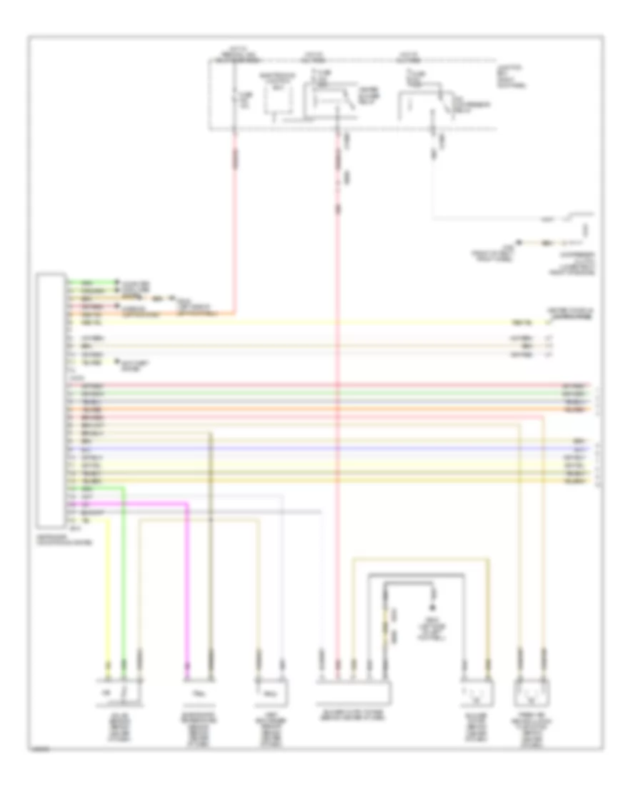
1.5L Turbo, Manual A/C Wiring Diagram (1 of 3) for MINI Cooper S 2014

List of elements for 1.5L Turbo, Manual A/C Wiring Diagram (1 of 3) for MINI Cooper S 2014:
- (not used)
- (rear of engine compt) refrigerant pressure sensor
- A/c compressor
- Auc sensor
- Audio control panel
- Basic
- Body domain controller
- Computer data lines system
- Control panel for heating & air conditioning
- Control valve
- Electronics junction box
- Front power distribution (left side of engine compt)
- Fuse 5a
- Fuse 7.5a
- Heating/air conditioning system
- High
- Hot w/ bistable relay energized
- Hot w/ terminal 15n relay energized
- Magnetic clutch
- Red
- X13 1b
- X434 1b
- Z10 1b
- Z10 3b
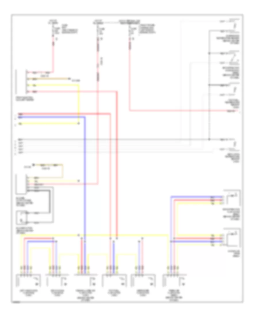
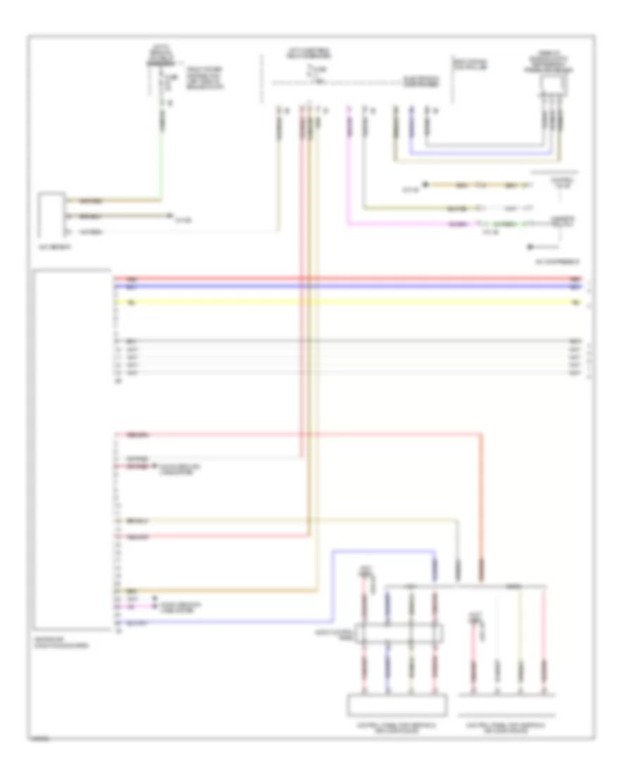
1.5L Turbo, Manual A/C Wiring Diagram (2 of 3) for MINI Cooper S 2014
List of elements for 1.5L Turbo, Manual A/C Wiring Diagram (2 of 3) for MINI Cooper S 2014:
- Air distribution flap motor (basic) (behind center of dash)
- Air distribution microswitch (basic) (behind center of dash)
- Blower motor (behind center of dash)
- Blower output stage (behind center of dash)
- Defroster flap motor (high)
- Evaporator temperature sensor (behind center of dash)
- Footwell flap motor (high)
- Footwell temperature sensor (high)
- Fresh air flap motor (basic) (behind center of dash)
- Front electric auxiliary heater
- Front power distribution (left side of engine compt)
- Fuse 100a
- Fuse 40a
- Fuse 5a
- Fuse box (right rear of engine compt)
- Hot at all times
- Hot w/ terminal 30b relay energized
- Left hand mixing flap drive (high)
- Mixing flap drive (basic)
- Nca
- Recirculated air flap motor (high) (behind center of dash)
- Red
- Right mixing flap drive (high)
- Ventilation temperature sensor (high)
- X126 1b
- X336 1b
- Z10 25b
- Z10 4b
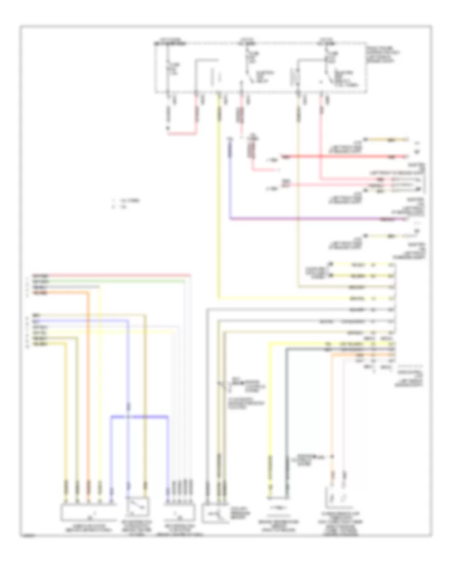
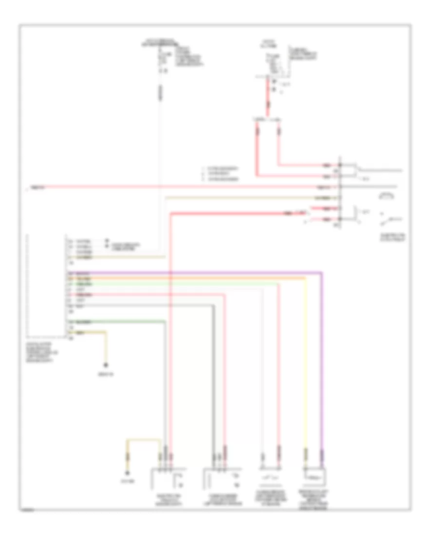
1.5L Turbo, Manual A/C Wiring Diagram (3 of 3) for MINI Cooper S 2014
List of elements for 1.5L Turbo, Manual A/C Wiring Diagram (3 of 3) for MINI Cooper S 2014:
- Characteristic map thermostat (top rear center of engine)
- Computer data lines system
- Digital motor electronics control module (left side of engine compt)
- Electric fan (front of engine compt)
- Electric fan cutout relay
- Engine coolant temperature sensor (top right rear side of engine)
- Front power distribution (left side of engine compt)
- Fuse 5a
- Fuse 60a 80a 125a
- Fuse box (right rear of engine compt)
- Hot at all times
- Hot w/ terminal 30b relay energized
- Red
- Turbocharger coolant pump (left rear of engine)
- W/ fan 200w/400w
- W/ fan 600w
- W/ fan 800w/850w
- Z10 15b
- Z6000 1b
1.6L
1.6L, Automatic A/C Wiring Diagram (1 of 2) for MINI Cooper S 2014
List of elements for 1.6L, Automatic A/C Wiring Diagram (1 of 2) for MINI Cooper S 2014:
- A/c compressor relay
- Anti-theft system
- Blower motor (behind center of dash)
- Blower output stage (behind center of dash)
- Center console control panel
- Compressor clutch (lower right front of engine)
- Computer data lines system
- Electronics junction box
- Evaporator temperature sensor (behind center of dash)
- Fresh air/ recirculation flap motor (behind center of dash)
- Fuse f20 10a
- Fuse f24 10a
- Fuse f48 30a
- Heat exchanger sensor (behind center of dash)
- Heater blower relay
- Heating/air conditioning system
- Hot at all times
- Hot w/ terminal 30g relay energized
- Interior lights system
- Junction box (right kick panel)
- Red
- Solar sensor (behind center of dash)
- X11007
- X11009
- X165 (front of right front wheel)
- X1879
- X2042 (left side of left footwell)
- X6056
- X610
- X9331
1.6L, Automatic A/C Wiring Diagram (2 of 2) for MINI Cooper S 2014
List of elements for 1.6L, Automatic A/C Wiring Diagram (2 of 2) for MINI Cooper S 2014:
- 1-tier
- 1.6l
- 1.6l turbo
- 2-tier
- Air distribution flap motor (behind center of dash)
- Air distribution microswitch (behind center of dash)
- Characteristic map thermostat (non turbo: right rear side of engine) (turbo: top rear center of engine)
- Computer data lines system
- Coolant pressure sensor
- Dme control unit (left side of engine compt)
- Electric fan (left front of engine compt)
- Electric fan relay
- Electric fan relay 2 (1.6l turbo)
- Engine controls system
- Engine temperature sensor (front of engine)
- Front power distribution box (left side of engine compt)
- Fuse f05 7.5a
- Fuse f08 40a
- Fuse fl9 50a
- Hot at all times
- Hot w/ dme relay energized
- Mixer flap motor (behind center of dash)
- Red
- W/ automatic engine start/stop function
- X175 (left front side of engine compt)
- X4007
- X4010
- X4013
- X4014
- X60004
- X60211
- X60231
1.6L, Manual A/C Wiring Diagram (1 of 2) for MINI Cooper S 2014
List of elements for 1.6L, Manual A/C Wiring Diagram (1 of 2) for MINI Cooper S 2014:
- A/c compressor relay
- Air distribution flap motor (behind center of dash)
- Air distribution microswitch (behind center of dash)
- Anti-theft system
- Center console control panel
- Compressor clutch (lower right front of engine)
- Computer data lines system
- Electronics junction box
- Evaporator temperature sensor (behind center of dash)
- Fresh air/ recirculation flap motor (behind center of dash)
- Fuse f20 10a
- Fuse f24 10a
- Fuse f48 30a
- Heater blower relay
- Heating/air conditioning system
- Hot at all times
- Hot w/ terminal 30g relay energized
- Interior lights system
- Junction box (right kick panel)
- Mixer flap motor (behind center of dash)
- Red
- X11007
- X11009
- X165 (front of right front wheel)
- X1879
- X2042 (left side of left footwell)
- X6056
- X610
- X611
1.6L, Manual A/C Wiring Diagram (2 of 2) for MINI Cooper S 2014
List of elements for 1.6L, Manual A/C Wiring Diagram (2 of 2) for MINI Cooper S 2014:
- 1-tier
- 1.6l
- 1.6l turbo
- 2-tier
- Blower ballast resistor
- Blower motor (behind center of dash)
- Characteristic map thermostat (non turbo: right rear side of engine) (turbo: top rear center of engine)
- Computer data lines system
- Coolant pressure sensor
- Dme control unit (left side of engine compt)
- Electric fan (left front of engine compt)
- Electric fan relay
- Electric fan relay 2 (1.6l turbo)
- Engine controls system
- Engine temperature sensor (front of engine)
- Front power distribution box (left side of engine compt)
- Fuse f05 7.5a
- Fuse f08 40a
- Fuse fl9 50a
- Hot at all times
- Hot w/ dme relay energized
- Red
- W/ automatic engine start stop function
- X175 (left front side of engine compt)
- X2042 (left side of left footwell)
- X4007
- X4010
- X4013
- X4014
- X60004
- X60211
- X60231
- X6056
- X9331
1.6L TURBO
1.6L Turbo, Automatic A/C Wiring Diagram (1 of 2) for MINI Cooper S 2014
List of elements for 1.6L Turbo, Automatic A/C Wiring Diagram (1 of 2) for MINI Cooper S 2014:
- A/c compressor relay
- Anti-theft system
- Blower motor (behind center of dash)
- Blower output stage (behind center of dash)
- Center console control panel
- Compressor clutch (lower right front of engine)
- Computer data lines system
- Electronics junction box
- Evaporator temperature sensor (behind center of dash)
- Fresh air/ recirculation flap motor (behind center of dash)
- Fuse f20 10a
- Fuse f24 10a
- Fuse f48 30a
- Heat exchanger sensor (behind center of dash)
- Heater blower relay
- Heating/air conditioning system
- Hot at all times
- Hot w/ terminal 30g relay energized
- Interior lights system
- Junction box (right kick panel)
- Red
- Solar sensor (behind center of dash)
- X11007
- X11009
- X165 (front of right front wheel)
- X1879
- X2042 (left side of left footwell)
- X6056
- X610
- X9331
1.6L Turbo, Automatic A/C Wiring Diagram (2 of 2) for MINI Cooper S 2014
List of elements for 1.6L Turbo, Automatic A/C Wiring Diagram (2 of 2) for MINI Cooper S 2014:
- 1-tier
- 1.6l
- 1.6l turbo
- 2-tier
- Air distribution flap motor (behind center of dash)
- Air distribution microswitch (behind center of dash)
- Characteristic map thermostat (non turbo: right rear side of engine) (turbo: top rear center of engine)
- Computer data lines system
- Coolant pressure sensor
- Dme control unit (left side of engine compt)
- Electric fan (left front of engine compt)
- Electric fan relay
- Electric fan relay 2 (1.6l turbo)
- Engine controls system
- Engine temperature sensor (front of engine)
- Front power distribution box (left side of engine compt)
- Fuse f05 7.5a
- Fuse f08 40a
- Fuse fl9 50a
- Hot at all times
- Hot w/ dme relay energized
- Mixer flap motor (behind center of dash)
- Red
- W/ automatic engine start/stop function
- X175 (left front side of engine compt)
- X4007
- X4010
- X4013
- X4014
- X60004
- X60211
- X60231
1.6L Turbo, Manual A/C Wiring Diagram (1 of 2) for MINI Cooper S 2014
List of elements for 1.6L Turbo, Manual A/C Wiring Diagram (1 of 2) for MINI Cooper S 2014:
- A/c compressor relay
- Air distribution flap motor (behind center of dash)
- Air distribution microswitch (behind center of dash)
- Anti-theft system
- Center console control panel
- Compressor clutch (lower right front of engine)
- Computer data lines system
- Electronics junction box
- Evaporator temperature sensor (behind center of dash)
- Fresh air/ recirculation flap motor (behind center of dash)
- Fuse f20 10a
- Fuse f24 10a
- Fuse f48 30a
- Heater blower relay
- Heating/air conditioning system
- Hot at all times
- Hot w/ terminal 30g relay energized
- Interior lights system
- Junction box (right kick panel)
- Mixer flap motor (behind center of dash)
- Red
- X11007
- X11009
- X165 (front of right front wheel)
- X1879
- X2042 (left side of left footwell)
- X6056
- X610
- X611
1.6L Turbo, Manual A/C Wiring Diagram (2 of 2) for MINI Cooper S 2014
List of elements for 1.6L Turbo, Manual A/C Wiring Diagram (2 of 2) for MINI Cooper S 2014:
- 1-tier
- 1.6l
- 1.6l turbo
- 2-tier
- Blower ballast resistor
- Blower motor (behind center of dash)
- Characteristic map thermostat (non turbo: right rear side of engine) (turbo: top rear center of engine)
- Computer data lines system
- Coolant pressure sensor
- Dme control unit (left side of engine compt)
- Electric fan (left front of engine compt)
- Electric fan relay
- Electric fan relay 2 (1.6l turbo)
- Engine controls system
- Engine temperature sensor (front of engine)
- Front power distribution box (left side of engine compt)
- Fuse f05 7.5a
- Fuse f08 40a
- Fuse fl9 50a
- Hot at all times
- Hot w/ dme relay energized
- Red
- W/ automatic engine start stop function
- X175 (left front side of engine compt)
- X2042 (left side of left footwell)
- X4007
- X4010
- X4013
- X4014
- X60004
- X60211
- X60231
- X6056
- X9331
2.0L TURBO
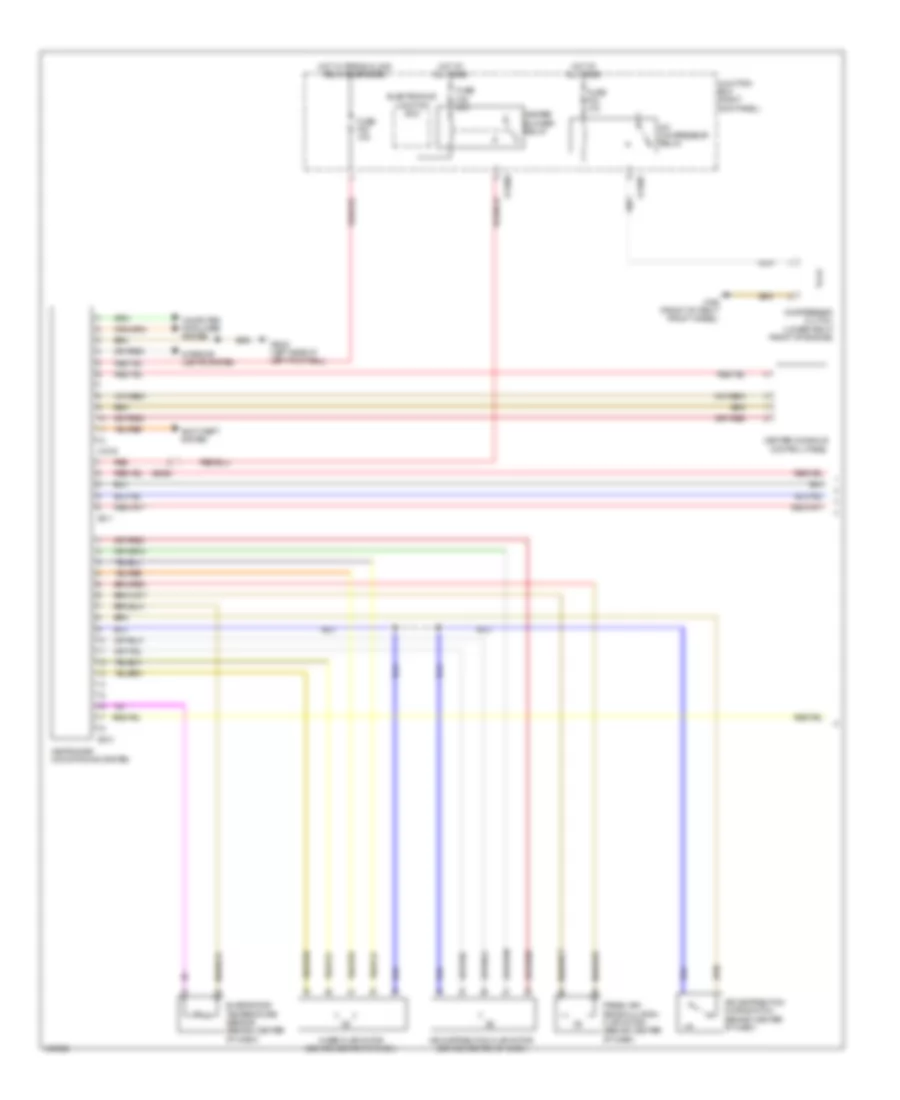
2.0L Turbo, Manual A/C Wiring Diagram (1 of 3) for MINI Cooper S 2014
List of elements for 2.0L Turbo, Manual A/C Wiring Diagram (1 of 3) for MINI Cooper S 2014:
- (not used)
- (rear of engine compt) refrigerant pressure sensor
- A/c compressor
- Auc sensor
- Audio control panel
- Basic
- Body domain controller
- Computer data lines system
- Control panel for heating & air conditioning
- Control valve
- Electronics junction box
- Front power distribution (left side of engine compt)
- Fuse 5a
- Fuse 7.5a
- Heating/air conditioning system
- High
- Hot w/ bistable relay energized
- Hot w/ terminal 15n relay energized
- Magnetic clutch
- Red
- X13 1b
- X434 1b
- Z10 1b
- Z10 3b
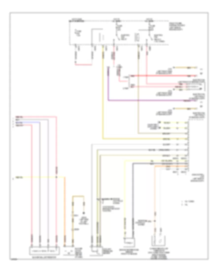
2.0L Turbo, Manual A/C Wiring Diagram (2 of 3) for MINI Cooper S 2014
List of elements for 2.0L Turbo, Manual A/C Wiring Diagram (2 of 3) for MINI Cooper S 2014:
- Air distribution flap motor (basic) (behind center of dash)
- Air distribution microswitch (basic) (behind center of dash)
- Blower motor (behind center of dash)
- Blower output stage (behind center of dash)
- Defroster flap motor (high)
- Evaporator temperature sensor (behind center of dash)
- Footwell flap motor (high)
- Footwell temperature sensor (high)
- Fresh air flap motor (basic) (behind center of dash)
- Front electric auxiliary heater
- Front power distribution (left side of engine compt)
- Fuse 100a
- Fuse 40a
- Fuse 5a
- Fuse box (right rear of engine compt)
- Hot at all times
- Hot w/ terminal 30b relay energized
- Left hand mixing flap drive (high)
- Mixing flap drive (basic)
- Nca
- Recirculated air flap motor (high) (behind center of dash)
- Red
- Right mixing flap drive (high)
- Ventilation temperature sensor (high)
- X126 1b
- X336 1b
- Z10 25b
- Z10 4b
2.0L Turbo, Manual A/C Wiring Diagram (3 of 3) for MINI Cooper S 2014
List of elements for 2.0L Turbo, Manual A/C Wiring Diagram (3 of 3) for MINI Cooper S 2014:
- Characteristic map thermostat (top rear center of engine)
- Computer data lines system
- Digital motor electronics control module (left side of engine compt)
- Electric fan (front of engine compt)
- Electric fan cutout relay
- Engine coolant temperature sensor (top right rear side of engine)
- Front power distribution (left side of engine compt)
- Fuse 5a
- Fuse 60a 80a 125a
- Fuse box (right rear of engine compt)
- Hot at all times
- Hot w/ terminal 30b relay energized
- Red
- Turbocharger coolant pump (left rear of engine)
- W/ fan 200w/400w
- W/ fan 600w
- W/ fan 800w/850w
- Z10 15b
- Z6000 1b