AIR CONDITIONING
Automatic A/C Wiring Diagram (1 of 2) for Mitsubishi Eclipse GT 2012

List of elements for Automatic A/C Wiring Diagram (1 of 2) for Mitsubishi Eclipse GT 2012:
- (behind left side of dash)
- A/c ecu (integral to heater control unit)
- A/c pressure sensor (right side of engine compt)
- Air mixing damper control motor & potentiometer (behind right side of dash)
- Air thermo sensor (behind center of dash, on heater unit)
- Ambient temperature sensor (near lower left side of radiator)
- C-15
- C-20
- C-21
- C24
- Defogger system
- Engine compartment relay box (left side of engine compt)
- Front ecu (in engine compt relay box)
- Fuse 10a
- Fuse 15a
- Fuse 7.5a
- Heater air intake duct sensor (under left side of dash, in air duct)
- Hot at all times
- Hot in acc or on
- Hot w/ taillight relay energized
- Illumination light relay
- Interior lights system
- Joint connector 1 (behind left side of dash)
- Joint connector 2 (behind left side of dash)
- Mode selection damper control motor & potentiometer (behind left side of dash)
- Nca
- Outside/inside air selection damper control motor (behind right side of dash, on hvac unit)
- Red
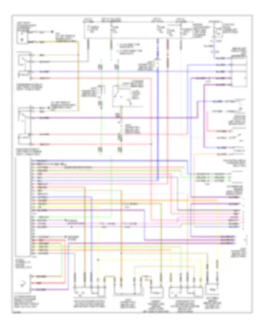
Automatic A/C Wiring Diagram (2 of 2) for Mitsubishi Eclipse GT 2012
List of elements for Automatic A/C Wiring Diagram (2 of 2) for Mitsubishi Eclipse GT 2012:
- (at left rear of engine compt, under relay box) g12
- A-15
- A-22
- A/c compressor assembly
- A/c compressor clutch
- A/c compressor clutch relay (in engine compt relay box)
- A/c refrigerant temperature switch
- A22-1
- B18
- B20
- B21
- Blower motor (behind right side of dash, on hvac unit)
- Blower relay
- C-203
- C-21
- C-24
- C202
- C215
- Computer data lines system
- Condenser fan motor (left front of engine compt)
- Connector (below left side of dash)
- Data link
- Engine compartment relay box (left side of engine compt)
- Engine controls system
- Engine coolant temperature sensor (on rear center of engine, near coolant outlet)
- Fan control module (attached to cooling fan shroud)
- Fan control relay (in engine compartment relay box)
- Fuse 10a
- Fuse 30a
- Fuse 7.5a
- Fusible link 2 50a
- G12 (at left rear of engine compt, under relay box)
- G4 (behind left side of dash)
- Hot at all times
- Hot in on
- Joint connector 1 (behind left side of dash)
- Joint connector 3 (behind left side of dash)
- Junction block (under left end of dash)
- Nca
- Off
- Power transistor (behind right side of dash)
- Powertrain control module (a/t) engine control module (m/t) (left side of engine compt, forward of relay box)
- Radiator fan motor (left front of engine compt)
- Red
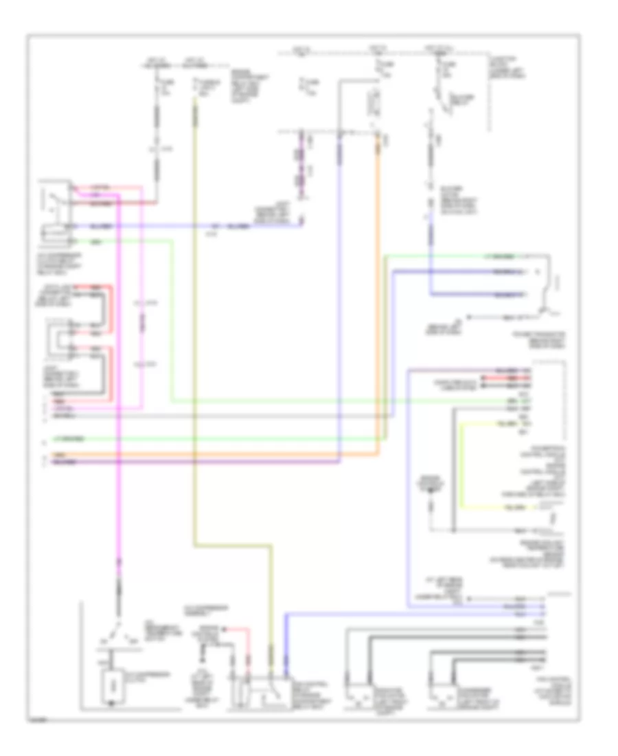
Manual A/C Wiring Diagram (1 of 2) for Mitsubishi Eclipse GT 2012
List of elements for Manual A/C Wiring Diagram (1 of 2) for Mitsubishi Eclipse GT 2012:
- (at left rear of engine compartment, under relay box) g12
- (behind left side of dash) joint connector 1
- (in engine compt relay box) front ecu
- (left front of engine compt) condenser fan motor
- A-15
- A/c ecu (integral to heater control unit)
- A/c pressure sensor (right side of engine compt)
- Air mixing damper control motor & potentiometer (behind right side of dash)
- Air thermo sensor (behind center of dash, on heater unit)
- Ambient temperature sensor (near lower left side of radiator)
- C-203
- C-21
- C-24
- C14
- C19
- C24
- Condenser fan relay (left front of engine compt, in relay box)
- Defogger system
- Engine compartment relay box (left side of engine compt)
- Fan control relay (in engine compt relay box)
- Fuse 10a
- Fuse 15a
- Fuse 7.5a
- Fusible link 2 30a
- Fusible link 26 20a
- G12 (at left rear of engine compt, under relay box)
- G3 (under center of dash)
- Headlights
- Hot at all times
- Hot in acc or on
- Hot in on
- Hot w/ taillight relay energized
- Illumi- nation light relay
- Interior lights system
- Joint connector 1 (behind left side of dash)
- Joint connector 2 (behind left side of dash)
- Junction block (under left end of dash)
- Mode selection damper control motor & potentiometer (behind left side of dash)
- Nca
- Outside/inside air selection damper control motor (behind right side of dash, on hvac unit)
- Radiator fan motor (left front of engine compt)
- Radiator fan relay (left front of engine compt, in relay box)
- Red
- W/ discharge type
- W/ halogen type headlights
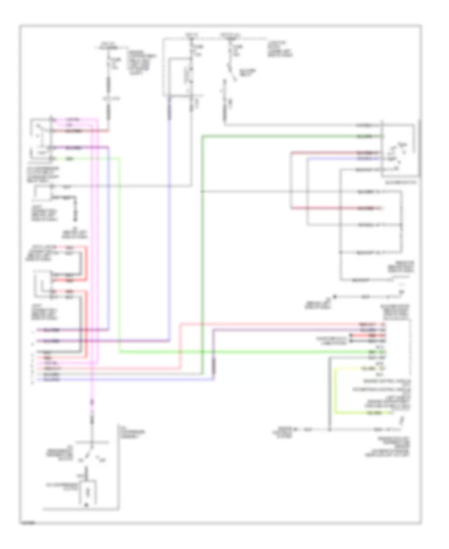
Manual A/C Wiring Diagram (2 of 2) for Mitsubishi Eclipse GT 2012
List of elements for Manual A/C Wiring Diagram (2 of 2) for Mitsubishi Eclipse GT 2012:
- A-15
- A/c compressor assembly
- A/c compressor clutch
- A/c compressor clutch relay (in engine compt relay box)
- A/c refrigerant temperature switch
- B-18
- B-20
- B-21
- Blower motor (behind right side of dash, on hvac unit)
- Blower relay
- Blower switch
- C-202
- C-215
- Computer data lines system
- Connector (below left side of dash)
- Data link
- Engine compartment relay box (left side of engine compt)
- Engine control module (m/t) powertrain control module (a/t) (left side of engine compartment, forward of relay box)
- Engine controls system
- Engine coolant temperature sensor (on rear of engine, near coolant outlet)
- Fuse 10a
- Fuse 30a
- Fuse 7.5a
- G4 (behind left side of dash)
- Hot at all times
- Hot in on
- Joint connector 2 (behind left side of dash)
- Joint connector 3 (behind left side of dash)
- Junction block (under left end of dash)
- Nca
- Off
- Red
- Resistor (behind right side of dash)