AIR CONDITIONING
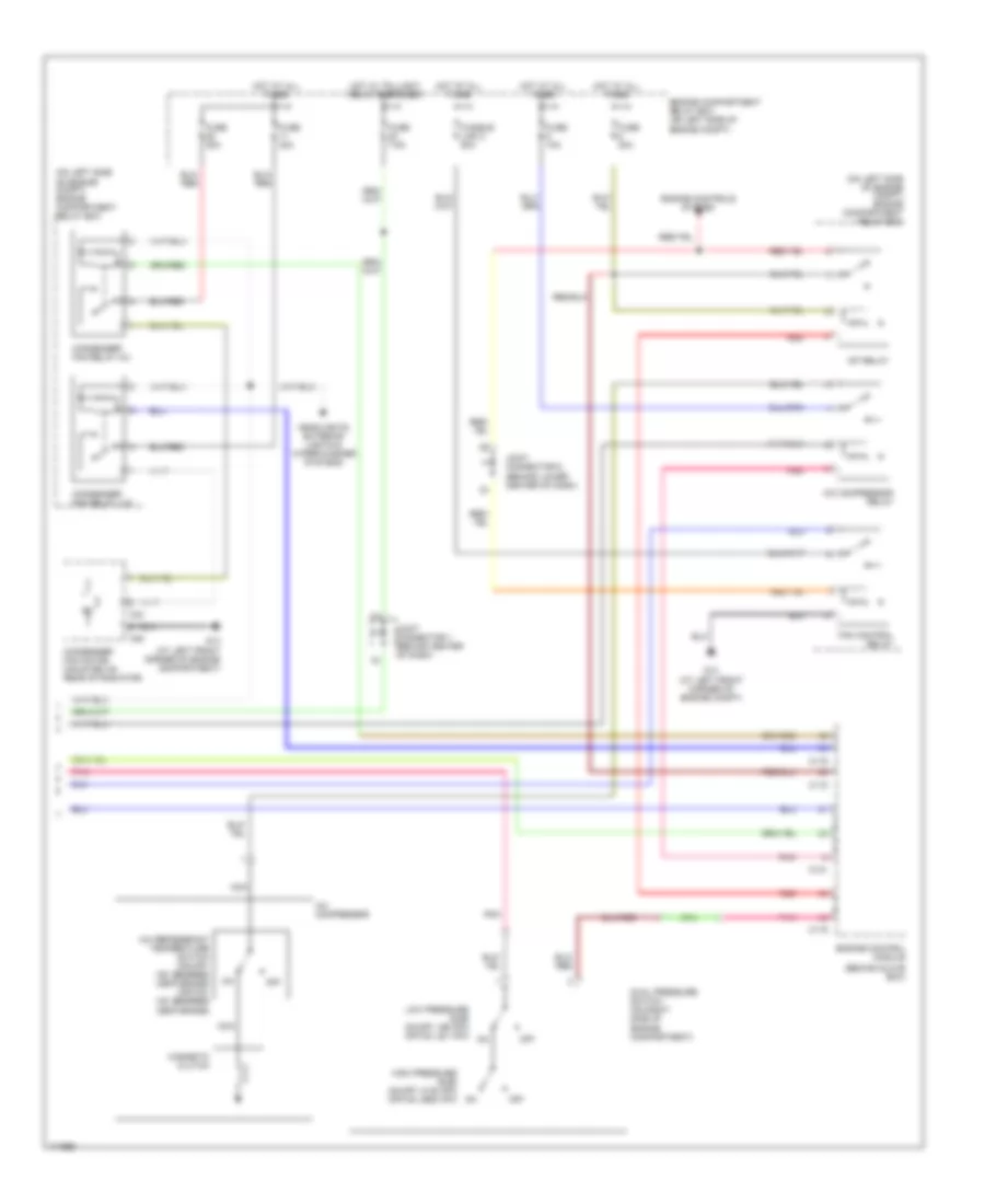
Manual A/C Wiring Diagram, Evolution (1 of 2) for Mitsubishi Lancer ES 2003

List of elements for Manual A/C Wiring Diagram, Evolution (1 of 2) for Mitsubishi Lancer ES 2003:
- (behind instrument cluster)
- A/c ecu (behind center of dash, below radio)
- A/c switch, outside/inside air selection damper control & illumination
- A17
- A17-1
- Air thermo sensor (behind right center of of dash, on hvac unit)
- Blower motor (behind right end of dash)
- Blower relay
- Blower switch
- C210
- C211
- C214
- Defogger system
- Fan control module (on fan shroud, at left front of engine compt)
- Fuse 30a
- Fuse 7.5a
- G13 (at left front corner of engine compartment)
- G3 (at right side of front deck crossmember)
- G6 (behind center of dash, near left center reinforcement)
- G7 (at top left side of dash)
- Hot at all times
- Hot in on
- Inlet side
- Interior lights system
- Joint connector 2
- Joint connector 3 (behind right side of dash)
- Junction block (behind left end of dash)
- Nca
- Off
- Outlet side
- Outside/inside air selection damper control motor (behind upper right end of dash)
- Pnk
- Radiator fan motor
- Resistor (behind right side of dash, on hvac unit)
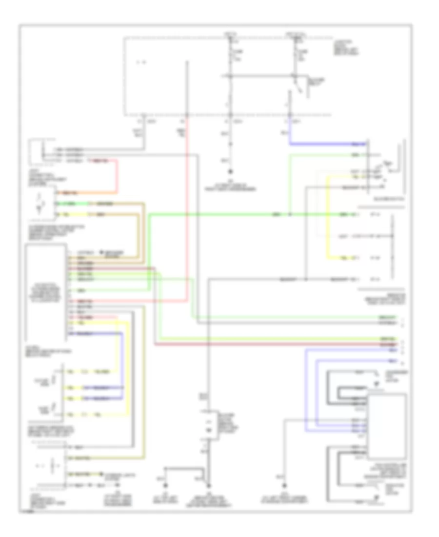
Manual A/C Wiring Diagram, Evolution (2 of 2) for Mitsubishi Lancer ES 2003
List of elements for Manual A/C Wiring Diagram, Evolution (2 of 2) for Mitsubishi Lancer ES 2003:
- (behind glove box)
- (on left side of engine compt) engine compartment relay box
- A/c compressor
- A/c compressor relay
- A/c refrigerant temperature switch (on-off: 150 degrees centigrade) (off-on: 120 degrees centigrade)
- A34
- A35
- C115
- C119
- C121
- Condenser fan motor (mounted on rear of radiator)
- Condenser fan relay (hi)
- Condenser fan relay (lo)
- Dual pressure switch (on right side of engine compartment)
- Engine compartment relay box (on left side of engine compt)
- Engine control module
- Engine controls system
- Fan control relay
- Fuse 10a
- Fuse 20a
- Fuse 30a
- Fuse 7.5a
- Fusible link 2 50a
- G13 (at left front corner of engine compartment)
- G13 (at left front corner of engine compt)
- Headlights, exterior lights & wiper/washer systems
- High pressure side on-off: 3138 kpa off-on: 2550 kpa
- Hot at all times
- Hot w/ taillight relay energized
- Joint connector 1 (behind center of dash)
- Joint connector 6 (behind lower center of dash)
- Low pressure side on-off: 196 kpa off-on: 221 kpa
- Magnetic clutch
- Mfi relay
- Nca
- Off
- Pnk
- Red
Manual A/C Wiring Diagram, Except Evolution (1 of 2) for Mitsubishi Lancer ES 2003
List of elements for Manual A/C Wiring Diagram, Except Evolution (1 of 2) for Mitsubishi Lancer ES 2003:
- (behind instrument cluster)
- A/c ecu (behind center of dash, below radio)
- A/c switch, outside/inside air selection damper control & illumination
- A17
- A17-1
- A17-2
- Air thermo sensor (a/c) (behind right center of of dash, on hvac unit)
- Blower motor (behind right end of dash)
- Blower relay
- Blower switch
- C210
- C211
- C214
- Condenser fan motor
- Defogger system
- Fan controller (on fan shroud, at left front of engine compartment)
- Fuse 30a
- Fuse 7.5a
- G13 (at left front corner of engine compartment)
- G3 (at right side of front deck crossmember)
- G6 (behind center of dash, near left center reinforcement)
- G7 (at top left side of dash)
- Hot at all times
- Hot in on
- Inlet side
- Interior lights system
- Joint connector 2
- Joint connector 3 (behind right side of dash)
- Junction block (behind left end of dash)
- Nca
- Off
- Outlet side
- Outside/inside air selection damper control motor (behind upper right end of dash)
- Radiator fan motor
- Resistor (behind right side of dash, on hvac unit)
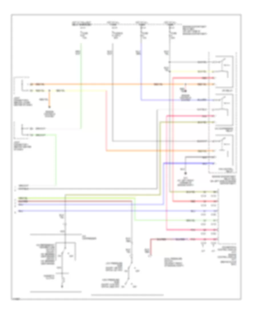
Manual A/C Wiring Diagram, Except Evolution (2 of 2) for Mitsubishi Lancer ES 2003
List of elements for Manual A/C Wiring Diagram, Except Evolution (2 of 2) for Mitsubishi Lancer ES 2003:
- (behind glove box)
- A/c compressor
- A/c compressor relay
- A/c refrigerant temperature switch (on-off: 150 degrees centigrade) (off-on: 120 degrees centigrade)
- A/t
- C115
- C116
- C118
- C119
- C120
- C121
- Dual pressure switch (on right front of engine compt)
- Engine compartment relay box (on left side of engine compartment)
- Engine control module (m/t)
- Engine controls system
- Fan control relay
- Fuse 10a
- Fuse 20a
- Fuse 7.5a
- Fusible link 2 50a
- G13 (at left front corner of engine compt)
- High pressure side on-off: 3138 kpa off-on: 2550 kpa
- Hot at all times
- Hot w/ taillight relay energized
- Joint connector 1 (behind center of dash)
- Joint connector 6 (behind lower center of dash)
- Low pressure side on-off: 196 kpa off-on: 221 kpa
- M/t
- Magnetic clutch
- Mfi relay
- Nca
- Off
- Pnk
- Powertrain control module (a/t)
- Red