AIR CONDITIONING
2.0L
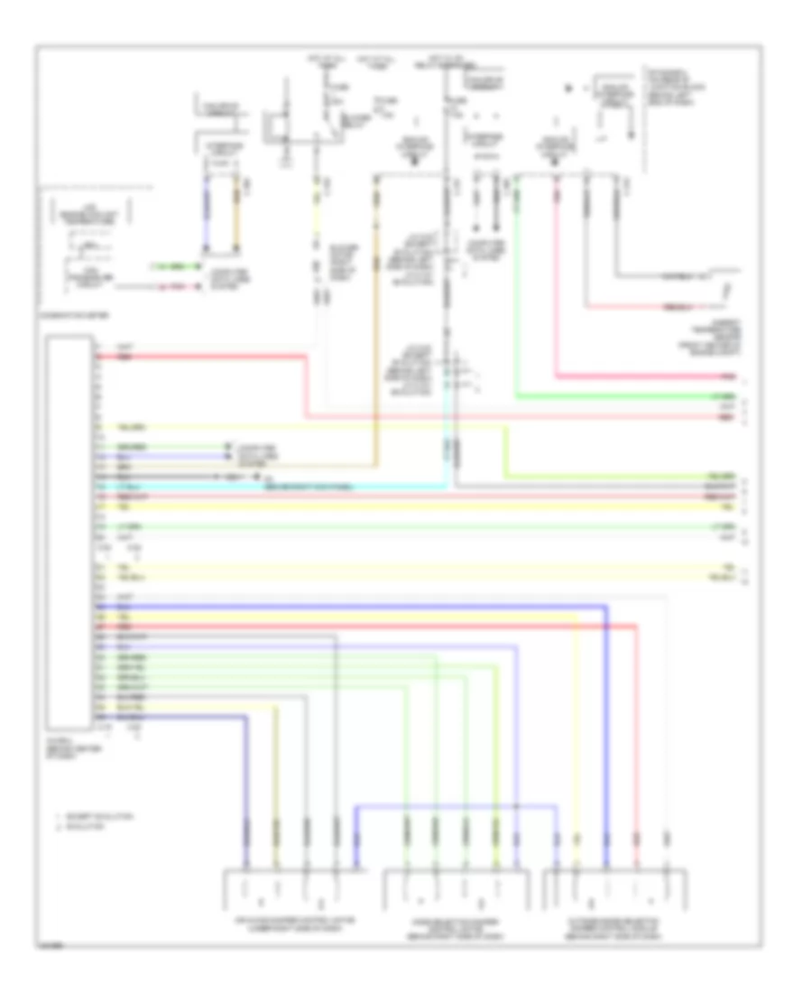
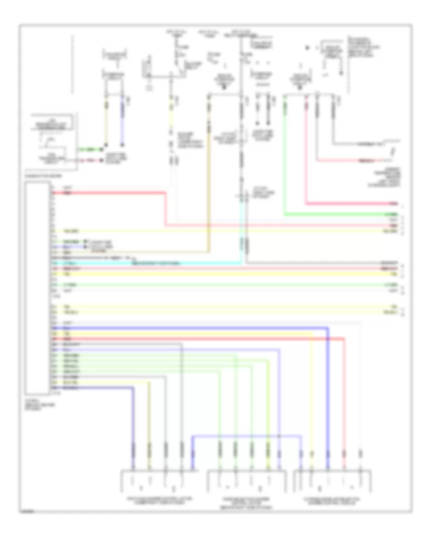
2.0L, Automatic A/C Wiring Diagram (1 of 3) for Mitsubishi Lancer GT 2012

List of elements for 2.0L, Automatic A/C Wiring Diagram (1 of 3) for Mitsubishi Lancer GT 2012:
- A/c-ecu (behind center of dash)
- Air mixing damper control motor (under right side of dash)
- Ambient temperature sensor (left front of engine compt)
- Analog interface circuit
- Blower motor (under right side of dash)
- Blower relay
- C-19
- C-20
- C-301
- C-312
- C-315
- C-317
- Can drive circuit
- Can transceiver circuit
- Combination meter
- Computer data lines system
- Cpu
- Etacs-ecu (on rear of junction block, behind left end of dash)
- Fuse 30a
- Fuse 7.5a
- G4 (behind right kick panel)
- Hot at all times
- Hot w/ ig1 relay energized
- Interface circuit
- J/c c-03 (right side of dash)
- Lcd (engine coolant temperature)
- Mode selection damper control motor (behind right side of dash)
- Outside/inside air selection damper control module
- Pnk
- Red
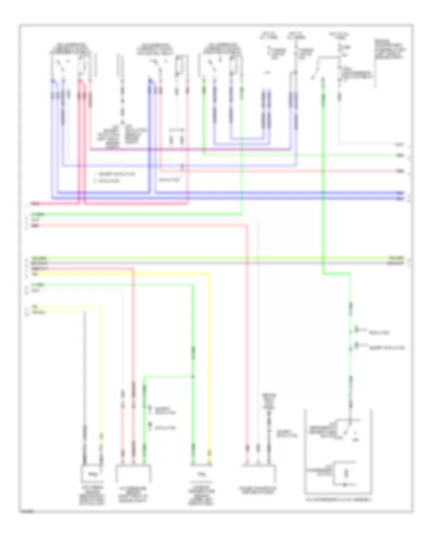
2.0L, Automatic A/C Wiring Diagram (2 of 3) for Mitsubishi Lancer GT 2012
List of elements for 2.0L, Automatic A/C Wiring Diagram (2 of 3) for Mitsubishi Lancer GT 2012:
- (left front of center console) g15
- (on underhood fuse/relay block) condenser fan relay
- (on underhood fuse/relay block) fan control relay
- (on underhood fuse/relay block) radiator fan relay
- A-10
- A/c compressor clutch
- A/c compressor clutch assembly
- A/c compressor clutch relay
- A/c pressure sensor (right front engine compt)
- A/c refrigerant temperature switch
- Air thermo sensor (behind right side of dash, on hvac unit)
- C-127
- Engine compartment fuse/relay box (left side of engine compt)
- Fuse 10a
- Fusible link 28 30a
- Fusible link 29 40a
- G17 (left front engine compt)
- Hot at all times
- Interior temperature sensor (under left side of dash)
- Nca
- Pnk
- Power transistor (under right side of dash)
- Red
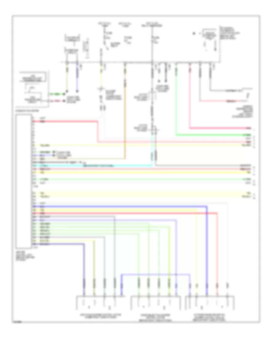
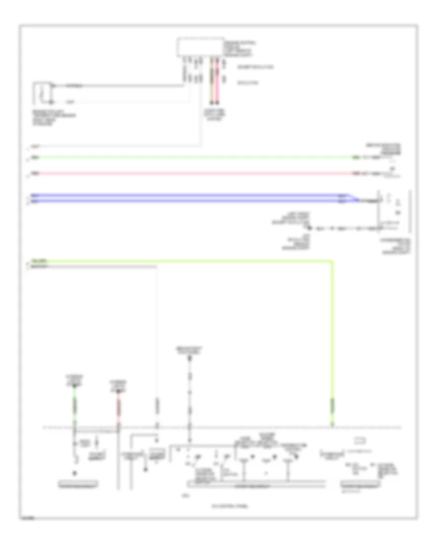
2.0L, Automatic A/C Wiring Diagram (3 of 3) for Mitsubishi Lancer GT 2012
List of elements for 2.0L, Automatic A/C Wiring Diagram (3 of 3) for Mitsubishi Lancer GT 2012:
- (behind right kick panel) g4
- A/c control panel
- A/c switch
- A/c switch ind
- B-108
- B-109
- Back light
- Blower speed selection dial
- Computer data lines system
- Condenser fan motor (front of engine compt)
- Cpu
- Engine control module (left rear of engine compt)
- Engine coolant temperature sensor (on rear of cylinder head)
- G17 (left front engine compt)
- Interface circuit
- Interior lights system
- Mode selection dial
- Nca
- Outside/ inside air selection ind
- Outside/ inside air selection switch
- Pnk
- Radiator fan motor (behind radiator)
- Red
- Temperature control dial
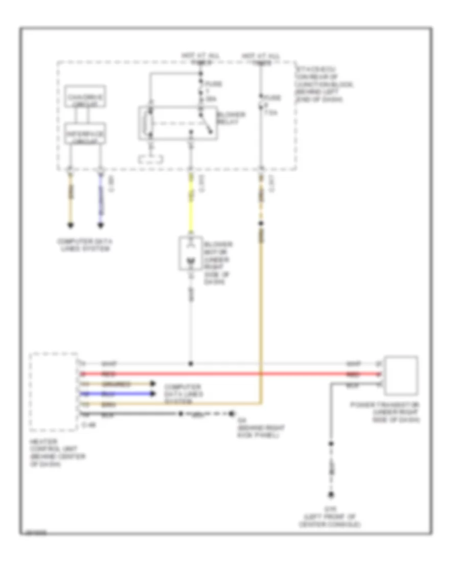
2.0L, Heater Wiring Diagram for Mitsubishi Lancer GT 2012
List of elements for 2.0L, Heater Wiring Diagram for Mitsubishi Lancer GT 2012:
- Blower motor (under right side of dash)
- Blower relay
- C-301
- C-315
- C-317
- C-48
- Can drive circuit
- Computer data lines system
- Etacs-ecu (on rear of junction block, behind left end of dash)
- Fuse 30a
- Fuse 7.5a
- G15 (left front of center console)
- G4 (behind right kick panel)
- Heater control unit (behind center of dash)
- Hot at all times
- Interface circuit
- Power transistor (under right side of dash)
- Red
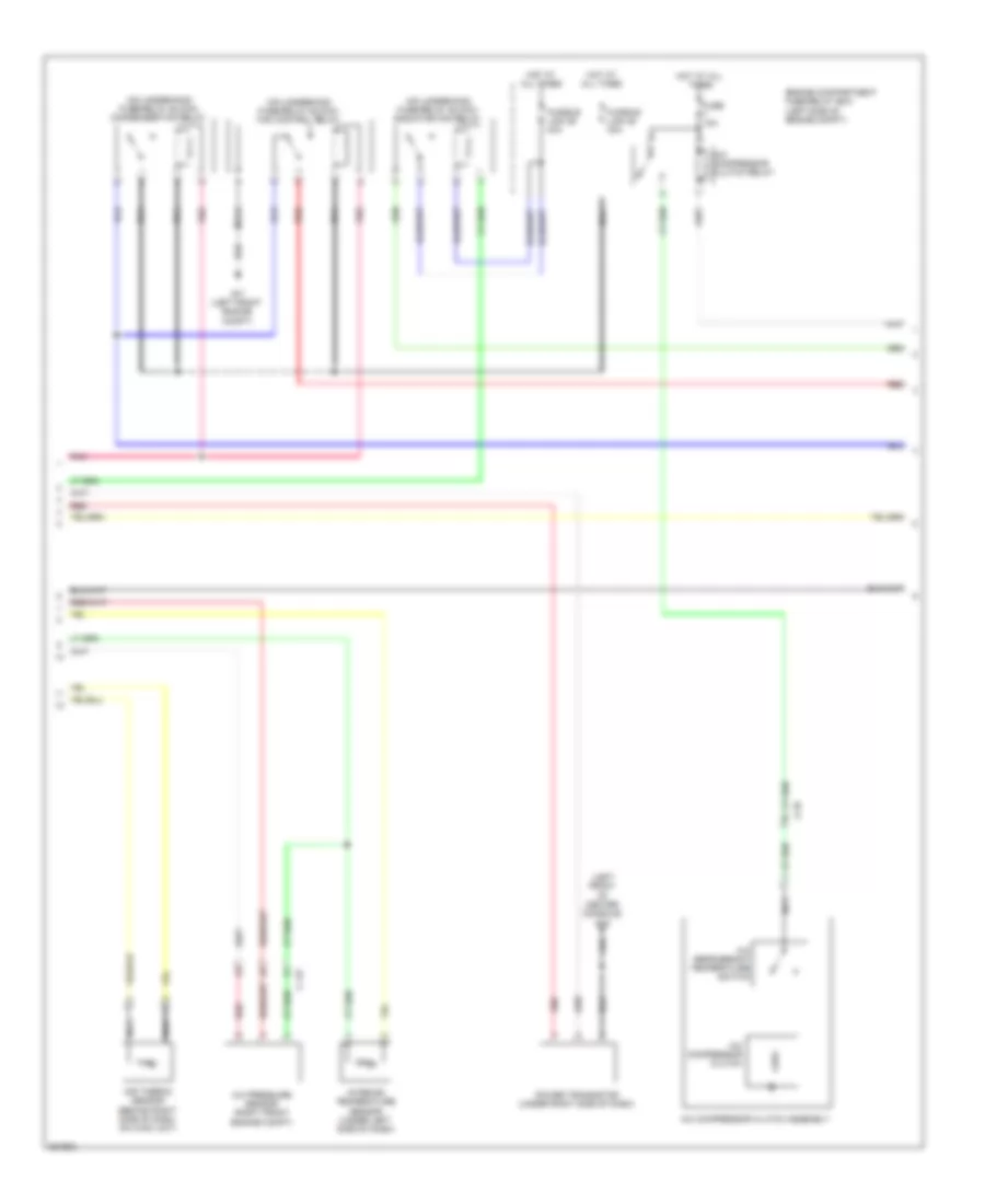
2.0L, Manual A/C Wiring Diagram (1 of 3) for Mitsubishi Lancer GT 2012
List of elements for 2.0L, Manual A/C Wiring Diagram (1 of 3) for Mitsubishi Lancer GT 2012:
- Air mixing damper control motor (under right side of dash)
- Ambient temperature sensor (left front of engine compt)
- Analog interface circuit
- Blower motor (under right side of dash)
- Blower relay
- C-301
- C-312
- C-315
- C-317
- C-47
- C-48
- Can drive circuit
- Can transceiver circuit
- Combination meter
- Computer data lines system
- Cpu
- Etacs-ecu (on rear of junction block, behind left end of dash)
- Fuse 30a
- Fuse 7.5a
- G4 (behind right kick panel)
- Heater control unit (behind center of dash)
- Hot at all times
- Hot w/ ig1 relay energized
- Interface circuit
- J/c c-03 (right side of dash)
- Lcd (engine coolant temperature)
- Mode selection damper control motor (behind right side of dash)
- Outside/inside selection damper control module (behind right side of dash)
- Pnk
- Red
2.0L, Manual A/C Wiring Diagram (2 of 3) for Mitsubishi Lancer GT 2012
List of elements for 2.0L, Manual A/C Wiring Diagram (2 of 3) for Mitsubishi Lancer GT 2012:
- (left front of center console) g15
- (not used)
- (on underhood fuse/relay block) condenser fan relay
- (on underhood fuse/relay block) fan control relay
- (on underhood fuse/relay block) radiator fan relay
- A-10
- A-42
- A/c compressor clutch
- A/c compressor clutch assembly
- A/c compressor clutch relay
- A/c refrigerant temperature switch
- Air thermo sensor (behind right side of dash, on hvac unit)
- C-08
- C-128
- Engine compartment fuse/relay box (left side of engine compt)
- Fuse 10a
- Fusible link 28 30a
- Fusible link 29 40a
- G17 (left front engine compt)
- Hot at all times
- Nca
- Pnk
- Power transistor (under right side of dash)
- Red
2.0L, Manual A/C Wiring Diagram (3 of 3) for Mitsubishi Lancer GT 2012
List of elements for 2.0L, Manual A/C Wiring Diagram (3 of 3) for Mitsubishi Lancer GT 2012:
- (behind right kick panel) g4
- B-108
- B-109
- Back light
- Blower speed selection dial
- Computer data lines system
- Condenser fan motor (front of engine compt)
- Cpu
- Engine control module (left rear of engine compt)
- Engine coolant temperature sensor (on rear of cylinder head)
- G17 (left front engine compt)
- Heater control panel
- Interface circuit
- Interior lights system
- Mode selection dial
- Nca
- Outside/ inside air selection ind
- Outside/ inside air selection switch
- Pnk
- Radiator fan motor (behind radiator)
- Red
- Temperature control dial
2.0L TURBO
2.0L Turbo, Automatic A/C Wiring Diagram (1 of 3) for Mitsubishi Lancer GT 2012
List of elements for 2.0L Turbo, Automatic A/C Wiring Diagram (1 of 3) for Mitsubishi Lancer GT 2012:
- A/c-ecu (behind center of dash)
- Air mixing damper control motor (under right side of dash)
- Ambient temperature sensor (front center of engine compt)
- Analog interface circuit
- Blower motor (right side of dash)
- Blower relay
- C-19
- C-20
- C-22
- C-301
- C-312
- C-315
- C-317
- Can drive circuit
- Can transceiver circuit
- Combination meter
- Computer data lines system
- Cpu
- Etacs-ecu (on rear of junction block, behind left end of dash)
- Evolution
- Except evolution
- Fuse 30a
- Fuse 7.5a
- G4 (behind right kick panel)
- Hot at all times
- Hot w/ ig1 relay energized
- Interface circuit
- J/c c-03 (except evolution) (behind left side of dash) j/c c-101 (evolution)
- Lcd (engine coolant temperature)
- Mode selection damper control motor (behind right side of dash)
- Outside/inside selection damper control module (behind right side of dash)
- Pnk
- Red
2.0L Turbo, Automatic A/C Wiring Diagram (2 of 3) for Mitsubishi Lancer GT 2012
List of elements for 2.0L Turbo, Automatic A/C Wiring Diagram (2 of 3) for Mitsubishi Lancer GT 2012:
- (behind right kick panel) g4
- (on underhood fuse/relay block) condenser fan relay
- (on underhood fuse/relay block) fan control relay
- (on underhood fuse/relay block) radiator fan relay
- (or red)
- A-13
- A-54
- A/c compressor clutch
- A/c compressor clutch assembly
- A/c compressor clutch relay
- A/c pressure sensor (right front of engine compt)
- A/c refrigerant temperature switch
- Air thermo sensor (behind right side of dash, on hvac unit)
- C-127
- C-130
- Engine compartment fuse/relay box (left side of engine compt)
- Evolution
- Except evolution
- Fuse 10a
- Fusible link 28 30a
- Fusible link 29 40a
- G16 (evolution) (rear of engine compt)
- G17 (except evolution) (left front engine compt)
- Hot at all times
- Interior temperature sensor (under left side of dash)
- Nca
- Off
- Pnk
- Power transistor (center of dash)
- Red
2.0L Turbo, Automatic A/C Wiring Diagram (3 of 3) for Mitsubishi Lancer GT 2012
List of elements for 2.0L Turbo, Automatic A/C Wiring Diagram (3 of 3) for Mitsubishi Lancer GT 2012:
- (behind radiator) radiator fan motor
- (behind right kick panel) g4
- (left front engine compt) (except evolution) g17
- A/c control panel
- A/c switch
- A/c switch ind
- B-09
- B-10
- B-108
- B-109
- Back light
- Blower speed selection dial
- Computer data lines system
- Condenser fan motor (front of engine compt)
- Cpu
- Engine control module (left rear of engine compt)
- Engine coolant temperature sensor (right rear of engine)
- Evolution
- Except evolution
- G16 (evolution) (rear of engine compt)
- Interface circuit
- Interior lights system
- Mode selection dial
- Nca
- Off
- Outside/ inside air selection ind
- Outside/ inside air selection switch
- Pnk
- Red
- Temperature control dial
2.4L
2.4L, Automatic A/C Wiring Diagram (1 of 3) for Mitsubishi Lancer GT 2012
List of elements for 2.4L, Automatic A/C Wiring Diagram (1 of 3) for Mitsubishi Lancer GT 2012:
- A/c-ecu (behind center of dash)
- Air mixing damper control motor (under right side of dash)
- Ambient temperature sensor (left front of engine compt)
- Analog interface circuit
- Blower motor (under right side of dash)
- Blower relay
- C-19
- C-20
- C-301
- C-312
- C-315
- C-317
- Can drive circuit
- Can transceiver circuit
- Combination meter
- Computer data lines system
- Cpu
- Etacs-ecu (on rear of junction block, behind left end of dash)
- Fuse 30a
- Fuse 7.5a
- G4 (behind right kick panel)
- Hot at all times
- Hot w/ ig1 relay energized
- Interface circuit
- J/c c-03 (right side of dash)
- Lcd (engine coolant temperature)
- Mode selection damper control motor (behind right side of dash)
- Outside/inside air selection damper control module
- Pnk
- Red
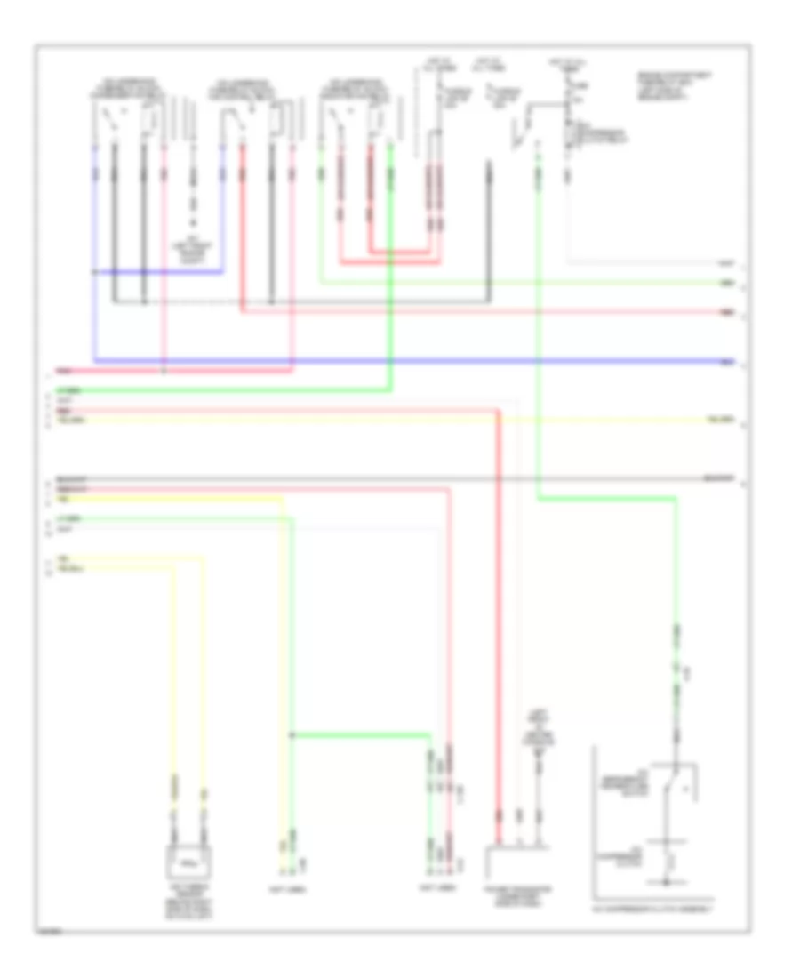
2.4L, Automatic A/C Wiring Diagram (2 of 3) for Mitsubishi Lancer GT 2012
List of elements for 2.4L, Automatic A/C Wiring Diagram (2 of 3) for Mitsubishi Lancer GT 2012:
- (left front of center console) g15
- (on underhood fuse/relay block) condenser fan relay
- (on underhood fuse/relay block) fan control relay
- (on underhood fuse/relay block) radiator fan relay
- A-10
- A/c compressor clutch
- A/c compressor clutch assembly
- A/c compressor clutch relay
- A/c pressure sensor (right front engine compt)
- A/c refrigerant temperature switch
- Air thermo sensor (behind right side of dash, on hvac unit)
- C-127
- Engine compartment fuse/relay box (left side of engine compt)
- Fuse 10a
- Fusible link 28 30a
- Fusible link 29 40a
- G17 (left front engine compt)
- Hot at all times
- Interior temperature sensor (under left side of dash)
- Nca
- Pnk
- Power transistor (under right side of dash)
- Red
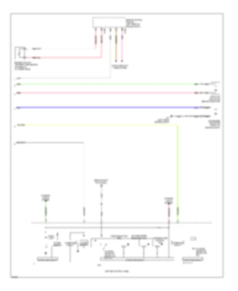
2.4L, Automatic A/C Wiring Diagram (3 of 3) for Mitsubishi Lancer GT 2012
List of elements for 2.4L, Automatic A/C Wiring Diagram (3 of 3) for Mitsubishi Lancer GT 2012:
- (behind right kick panel) g4
- A/c control panel
- A/c switch
- A/c switch ind
- B-108
- B-109
- Back light
- Blower speed selection dial
- Computer data lines system
- Condenser fan motor (front of engine compt)
- Cpu
- Engine control module (left rear of engine compt)
- Engine coolant temperature sensor (on rear of cylinder head)
- G17 (left front engine compt)
- Interface circuit
- Interior lights system
- Mode selection dial
- Nca
- Outside/ inside air selection ind
- Outside/ inside air selection switch
- Pnk
- Radiator fan motor (behind radiator)
- Red
- Temperature control dial
2.4L, Manual A/C Wiring Diagram (1 of 3) for Mitsubishi Lancer GT 2012
List of elements for 2.4L, Manual A/C Wiring Diagram (1 of 3) for Mitsubishi Lancer GT 2012:
- Air mixing damper control motor (under right side of dash)
- Ambient temperature sensor (left front of engine compt)
- Analog interface circuit
- Blower motor (under right side of dash)
- Blower relay
- C-301
- C-312
- C-315
- C-317
- C-47
- C-48
- Can drive circuit
- Can transceiver circuit
- Combination meter
- Computer data lines system
- Cpu
- Etacs-ecu (on rear of junction block, behind left end of dash)
- Fuse 30a
- Fuse 7.5a
- G4 (behind right kick panel)
- Heater control unit (behind center of dash)
- Hot at all times
- Hot w/ ig1 relay energized
- Interface circuit
- J/c c-03 (right side of dash)
- Lcd (engine coolant temperature)
- Mode selection damper control motor (behind right side of dash)
- Outside/inside selection damper control module (behind right side of dash)
- Pnk
- Red
2.4L, Manual A/C Wiring Diagram (2 of 3) for Mitsubishi Lancer GT 2012
List of elements for 2.4L, Manual A/C Wiring Diagram (2 of 3) for Mitsubishi Lancer GT 2012:
- (left front of center console) g15
- (not used)
- (on underhood fuse/relay block) condenser fan relay
- (on underhood fuse/relay block) fan control relay
- (on underhood fuse/relay block) radiator fan relay
- A-10
- A-42
- A/c compressor clutch
- A/c compressor clutch assembly
- A/c compressor clutch relay
- A/c refrigerant temperature switch
- Air thermo sensor (behind right side of dash, on hvac unit)
- C-08
- C-128
- Engine compartment fuse/relay box (left side of engine compt)
- Fuse 10a
- Fusible link 28 30a
- Fusible link 29 40a
- G17 (left front engine compt)
- Hot at all times
- Nca
- Pnk
- Power transistor (under right side of dash)
- Red
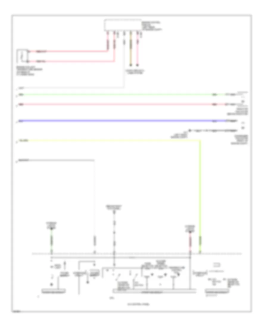
2.4L, Manual A/C Wiring Diagram (3 of 3) for Mitsubishi Lancer GT 2012
List of elements for 2.4L, Manual A/C Wiring Diagram (3 of 3) for Mitsubishi Lancer GT 2012:
- (behind right kick panel) g4
- B-108
- B-109
- Back light
- Blower speed selection dial
- Computer data lines system
- Condenser fan motor (front of engine compt)
- Cpu
- Engine control module (left rear of engine compt)
- Engine coolant temperature sensor (on rear of cylinder head)
- G17 (left front engine compt)
- Heater control panel
- Interface circuit
- Interior lights system
- Mode selection dial
- Nca
- Outside/ inside air selection ind
- Outside/ inside air selection switch
- Pnk
- Radiator fan motor (behind radiator)
- Red
- Temperature control dial