AIR CONDITIONING
A/C Wiring Diagram for Mitsubishi Montero SR 1997

List of elements for A/C Wiring Diagram for Mitsubishi Montero SR 1997:
- A/c
- Air conditioning compressor clutch relay (left side of engine compt)
- Air conditioning compressor magnetic clutch (front left of engine compt)
- Air conditioning control unit (right side of i/p)
- Air conditioning switch (center of i/p)
- Air inlet sensor (right side of i/p)
- Air thermo sensor (right side of i/p)
- Blower motor (right side of i/p)
- Blower motor relay
- Blower resistor (right side of i/p)
- Blower switch (center of i/p)
- C 1995 vftc
- C36
- C37
- Condenser fan motor (front left of engine compt)
- Condenser fan motor relay (left side of engine compt)
- Dual pressure switch (front left of engine compt)
- Eco
- Engine control module (right side of i/p)
- Fuse 16 25a
- Fuse 2 10a
- Fuse 3 10a
- Fuse 3 25a
- G100 (left front fender)
- G202 (left side of i/p)
- Heater control illumination light (center of i/p)
- Hot at all times
- Hot in run
- Interior lights system (fuse #5)
- Interior lights system (rheostat)
- Junction block (left side of i/p)
- Off
- Relay box (left side of engine compt)
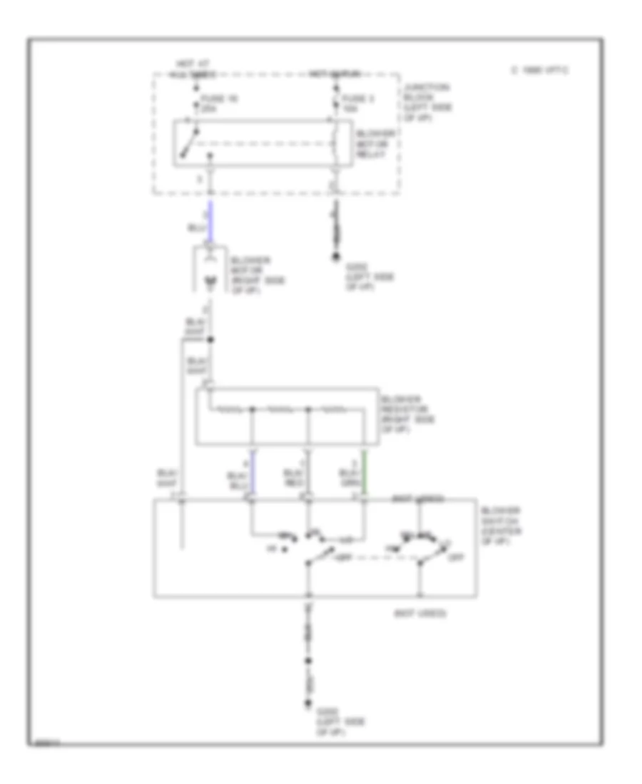
Heater Wiring Diagram for Mitsubishi Montero SR 1997
List of elements for Heater Wiring Diagram for Mitsubishi Montero SR 1997:
- (not used)
- Blower motor (right side of i/p)
- Blower motor relay
- Blower resistor (right side of i/p)
- Blower switch (center of i/p)
- C 1995 vftc
- Fuse 16 25a
- Fuse 3 10a
- G202 (left side of i/p)
- Hot at all times
- Hot in run
- Junction block (left side of i/p)
- Off