AIR CONDITIONING
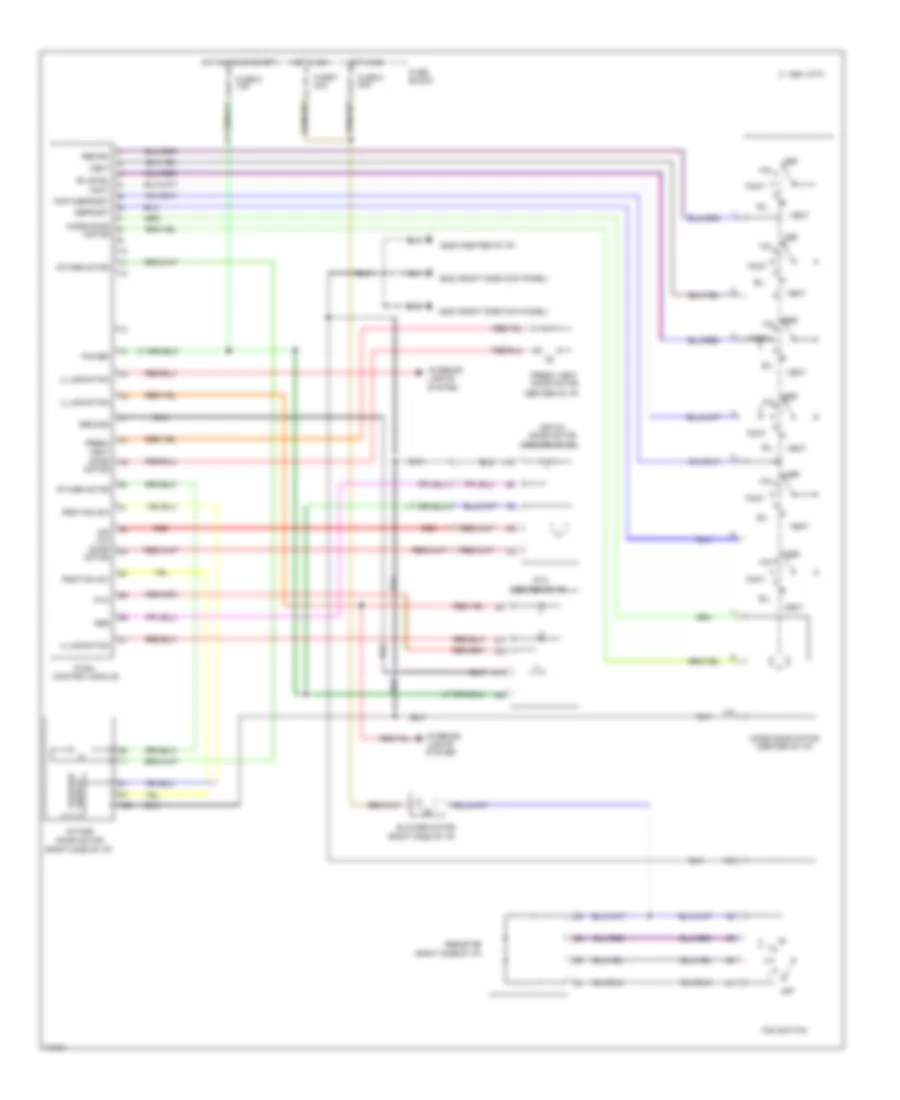
A/C Wiring Diagram, Auto A/C (1 of 2) for Nissan Altima SE 1996

List of elements for A/C Wiring Diagram, Auto A/C (1 of 2) for Nissan Altima SE 1996:
- (center g206
- (center of i/p)
- (left side
- (right de-
- (right rear of engine)
- (right side g203
- (right side of i/p)
- +5v
- 1994 vftc c
- A/mix actr
- A/mix pbr
- Air mix door motor
- Amb sen
- Ambient sensor (center front
- Auto amp
- B/l
- Bat
- Blower hi relay (right side of i/p)
- Blower motor
- Blwr rly
- Def
- Engine control module (below center console)
- F/d
- Fan control amp
- Fan f/b
- Fan gate
- Fascia)
- Foot
- Fresh vent door motor
- Froster grille)
- Fuse 10a
- Fuse 20a
- Fuse 26 10a
- Fuse block
- Fv actr
- Gnd
- Hot at all times
- Hot in on
- I/p)
- Ign
- Ill
- In vehicle sensor
- Incar sens
- Intake 20% fre/fre
- Intake actr
- Intake door motor
- Intake fre/rec
- Intake rec 20% fre
- Interior lights system
- Kick panel)
- Mode actr
- Mode def b/l foot
- Mode door motor (center of i/p)
- Mode f/d def
- Mode foot f/d vent
- Mood vent
- Of i/p)
- Or start
- Pnk
- Position switch
- Psdw
- Red
- Sens gnd
- Sun sensor
- Sunload sensor
- Thermal transmitter
- Thermo amp
- Thermo amp
- Thermo control amp
- Triple pressure switch (left front of engine compt)
- Vent
- W/t sens
A/C Wiring Diagram, Auto A/C (2 of 2) for Nissan Altima SE 1996
List of elements for A/C Wiring Diagram, Auto A/C (2 of 2) for Nissan Altima SE 1996:
- (left front g100
- (right g101
- 1994 vftc c
- A/c compressor clutch
- A/c relay (relay box 1, right front of engine compt)
- Acrly
- Cooling fan motor 1
- Cooling fan motor 2
- Cooling fan relay 1 (relay box 2, left front of engine compt)
- Cooling fan relay 2 (relay box 1, right front of engine compt)
- Cooling fan relay 3 (relay box 1, right front of engine compt)
- Engine control module (under center console)
- Fender)
- Front fender)
- Fuse 10a
- Fuse 4 10a
- Fuse box
- Fusible link f 30a
- Fusible link h 30a
- Fusible link box
- Fusible link e 75a
- Hot at all times
- Hot in on and start
- Idle air control valve (right rear of engine)
- J/c
- J/c 1
- J/c 2
- Nca
- Rfrh
- Rfrl
- Thermal protector
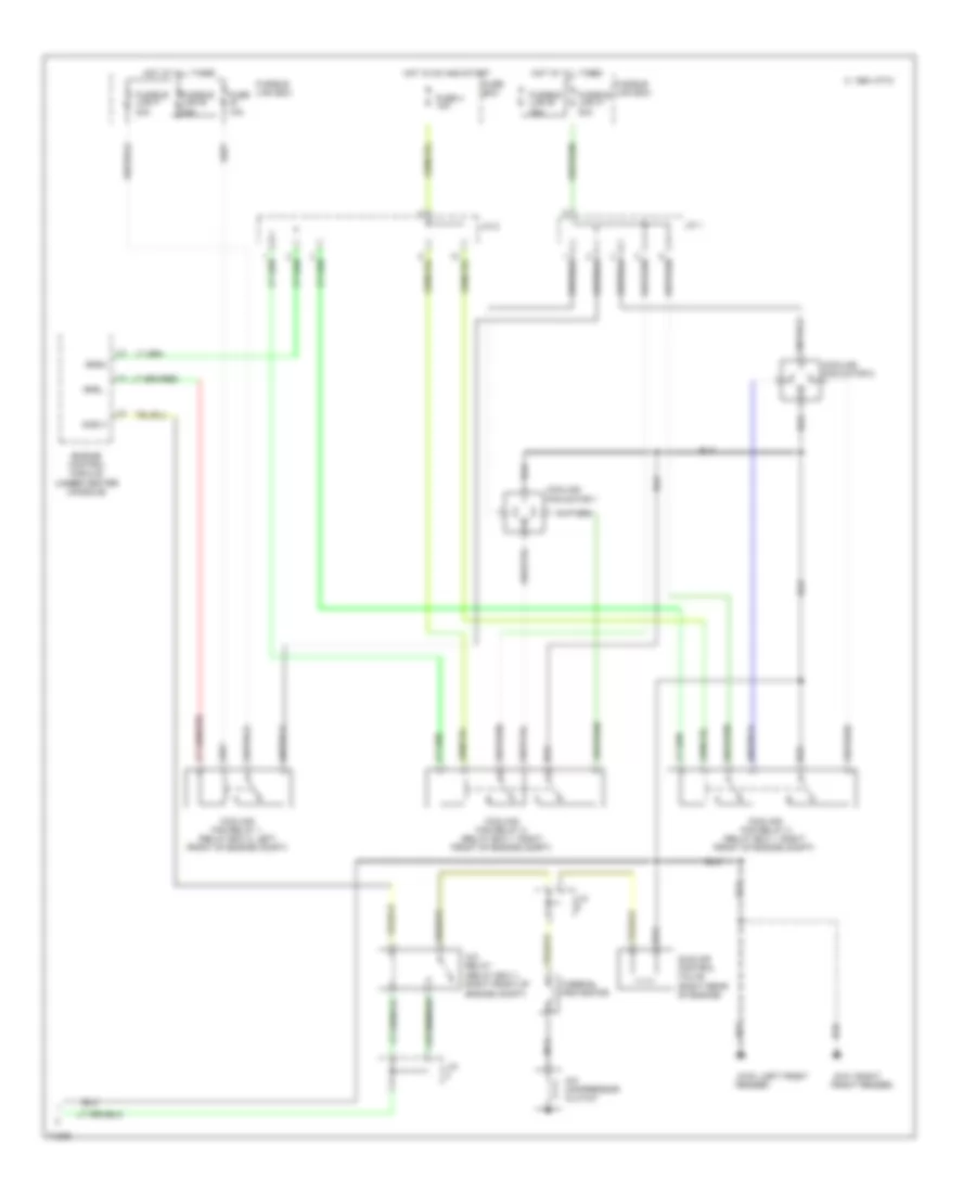
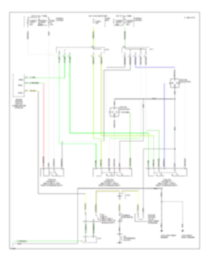
A/C Wiring Diagram, Manual A/C (1 of 2) for Nissan Altima SE 1996
List of elements for A/C Wiring Diagram, Manual A/C (1 of 2) for Nissan Altima SE 1996:
- (+) cold (-) hot
- (+) fre (-) rec
- (+) open (-) close
- (+) vent/(-) def
- (-) cold (+) hot
- (-) fre (+) rec
- (-) open (+) close
- (-) vent/(+) def
- (center of i/p)
- (center of i/p) g206
- (right side kick panel) g203
- (right side of i/p)
- 1994 vftc c
- A/c sw
- A/c switch
- Air mix door motor
- B/l
- B/l input
- Blower motor
- Console)
- Def
- Def input
- Engine control module (under center
- F/d
- F/d input
- Fan switch
- Foot
- Foot input
- Fre input
- Fresh vent door motor
- Fuse 6 10a
- Fuse 7 20a
- Fuse 8 20a
- Fuse block
- Ground
- Hot in on
- Hot in on or start
- Ign
- Ill
- Intake door motor
- Interior lights system
- Mode door motor (center of i/p)
- Off
- Pbr
- Psdw
- Ptc
- Push control module
- Rec input
- Red
- Resistor
- Switch position
- Thermo amp
- Thermo control amp
- Triple pressure switch (left front of engine compt)
- Vent
- Vent input
A/C Wiring Diagram, Manual A/C (2 of 2) for Nissan Altima SE 1996
List of elements for A/C Wiring Diagram, Manual A/C (2 of 2) for Nissan Altima SE 1996:
- (left front g100
- (right g101
- 1994 vftc c
- A/c compressor clutch
- A/c relay (relay box 1, right front of engine compt)
- Acrly
- Cooling fan motor 1
- Cooling fan motor 2
- Cooling fan relay 1 (relay box 2, left front of engine compt)
- Cooling fan relay 2 (relay box 1, right front of engine compt)
- Cooling fan relay 3 (relay box 1, right front of engine compt)
- Engine control module (under center console)
- Fender)
- Front fender)
- Fuse 10a
- Fuse 4 10a
- Fuse box
- Fusible link f 30a
- Fusible link h 30a
- Fusible link box
- Fusible link e 75a
- Hot at all times
- Hot in on and start
- Idle air control valve (right rear of engine)
- J/c 1
- J/c 2
- J/c 6
- Nca
- Rfrh
- Rfrl
- Thermal protector
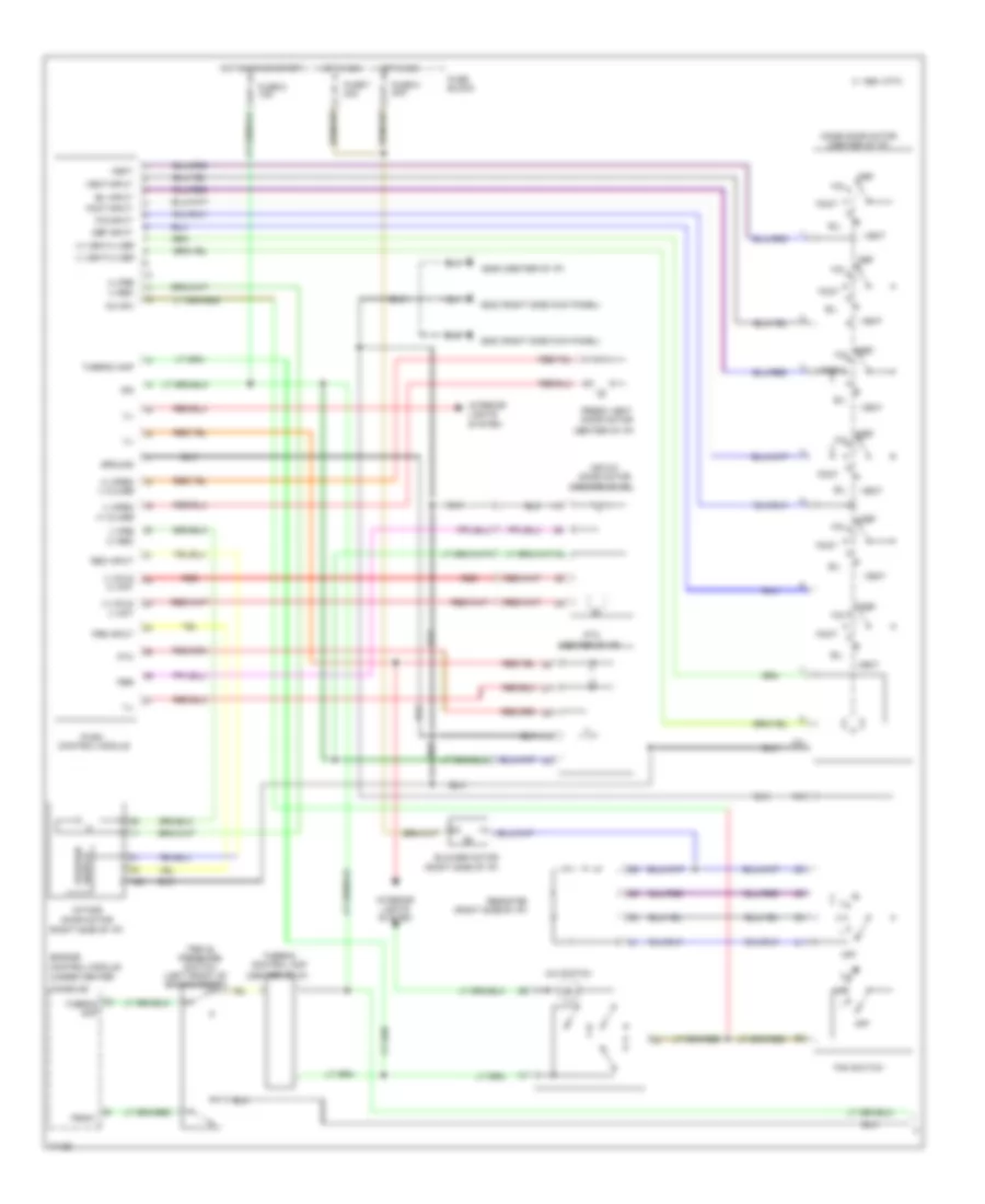
Heater Wiring Diagram for Nissan Altima SE 1996
List of elements for Heater Wiring Diagram for Nissan Altima SE 1996:
- (center of i/p)
- (center of i/p) g206
- (right side kick panel) g203
- (right side of i/p)
- 1994 vftc c
- Air mix
- Air mix door motor
- B/l
- Bi-level
- Blower motor
- Def
- Defrost
- Door motor
- F/d
- Fan switch
- Foot
- Foot/defrost
- Fresh vent
- Fresh vent door motor
- Fuse 6 10a
- Fuse 7 20a
- Fuse 8 20a
- Fuse block
- Ground
- Hot in on
- Hot in on or start
- Illumination
- Intake door motor
- Intake motor
- Interior lights system
- Mode door motor
- Mode door motor (center of i/p)
- Off
- Pbr
- Position sw
- Power
- Ptc
- Push control module
- Recirc
- Red
- Resistor
- Switch position
- Vent