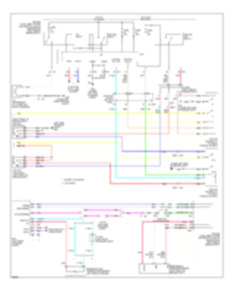
AIR CONDITIONING
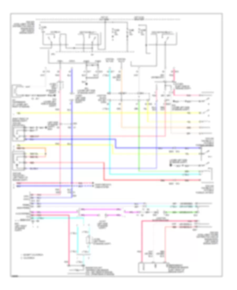
Automatic A/C Wiring Diagram, Coupe (1 of 2) for Nissan Altima SV 2013

List of elements for Automatic A/C Wiring Diagram, Coupe (1 of 2) for Nissan Altima SV 2013:
- (behind right end of dash) m61
- 23g
- 25g
- 2n m3
- 32g
- 3n m3
- 5n m3
- 6p e6
- 6q m4
- 7m m5
- A/c pd cut
- Acc
- Aircon sw
- Amb sens
- Amb vdd
- Ambient sensor (behind lower left side of front grille)
- Batt
- Blower motor (behind lower right side of dash)
- Body control module (bcm) (behind left side of dash)
- Bwr fan sw
- Can-h
- Can-l
- Combination meter
- Comp on
- Defogger system
- E12
- E18
- E201
- E203
- E30
- Fan on
- Fan pwm
- Front air control
- Front blower motor relay
- Fuse & fusible link box (left front of engine compt, near ipdm e/r)
- Fuse 10a
- Fuse 15a
- Fuse block (j/b) (behind left end of dash)
- Fusible link k 40a
- Fusible link m 40a
- Gnd
- Gnd (oat sens)
- Gnd (pwr)
- Hot at all times
- Hot in on or acc
- Hot in on or start
- Ign
- Ign 2
- Ign2 cont
- Ill+
- Ill-
- In-vehicle sensor (left center of dash, near ignition switch)
- Inc sens
- Int sens
- Intake door motor (right side of blower housing)
- Intake sensor (behind right side of dash, on hvac assembly)
- Interior lights system
- Ipdm e/r (intelligent power distribution module engine room) (left side of engine compt)
- J/c e01 (left side of engine compt)
- Lan sig
- Left air mix door motor (left side hvac unit)
- M1 e30
- M125
- M18
- M19
- M33
- M57 (behind left end of dash)
- M61 (behind right end of dash)
- Mode door motor (left side hvac unit)
- Oat
- Oat pwr
- Pd cut
- Pnk
- Right air mix door motor (right side hvac unit)
- Rr def f/b
- Rr def on
- Sens gnd
- Sun sens
- Sunload sensor (upper left side of dash, near base of windshield)
- Vactr
- W/t temp
- Water temp out
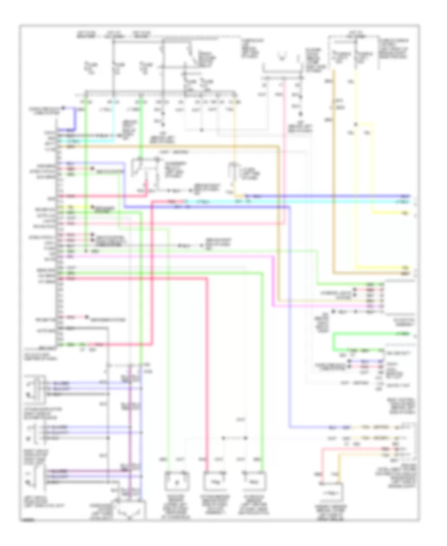
Automatic A/C Wiring Diagram, Coupe (2 of 2) for Nissan Altima SV 2013
List of elements for Automatic A/C Wiring Diagram, Coupe (2 of 2) for Nissan Altima SV 2013:
- (left side of engine compt) e204
- (lower left side of engine compt) e9
- (right front of engine compt) cooling fan motor 2
- 15g
- 51g m1
- 52g
- A/c compressor (at lower left front of engine)
- A/c relay
- Avcc-pdpres
- Avcc2
- California
- Can-h
- Can-l
- Computer data lines system
- Cooling fan motor 1 (left front of engine compt)
- Cooling fan relay 1
- Cooling fan relay 2 (in fuse & fusible link box)
- Cooling fan relay 3 (in fuse & fusible link box)
- Cpu
- E10
- E12
- E15 (lower left side of engine compt)
- E17
- E18
- E201
- E203
- E203 e12
- E30
- E31
- E44
- E45
- E47
- E48
- Ecm (left front of engine compt)
- Engine coolant temperature sensor (2.5l: left rear of engine) (3.5l: upper rear of engine)
- Except california
- F10
- F13
- F2 b11
- F90
- Fuse 10a
- Fuse 15a
- Gnd
- Gnda-pdres
- Gnda-tw
- Hot at all times
- Hot in on or start
- Ig+
- Ignition relay 1
- Ipdm e/r (intelligent power distribution module engine room) (left side of engine compt)
- J/c e02 (left side of engine compt)
- J/c e03 (left side of engine compt)
- J/c e04 (left side of engine compt)
- J/c f06 (left front of engine compt)
- J/c f07 (left side of engine compt)
- Junction block e44 & e45
- Junction block e44, e47 & e48
- Mtr fan rly hi
- Mtr fan rly mid
- P-gnd
- Pdres
- Pnk
- Red
- Refrigerant pressure sensor (left front of engine compt)
- S-gnd
- Sig
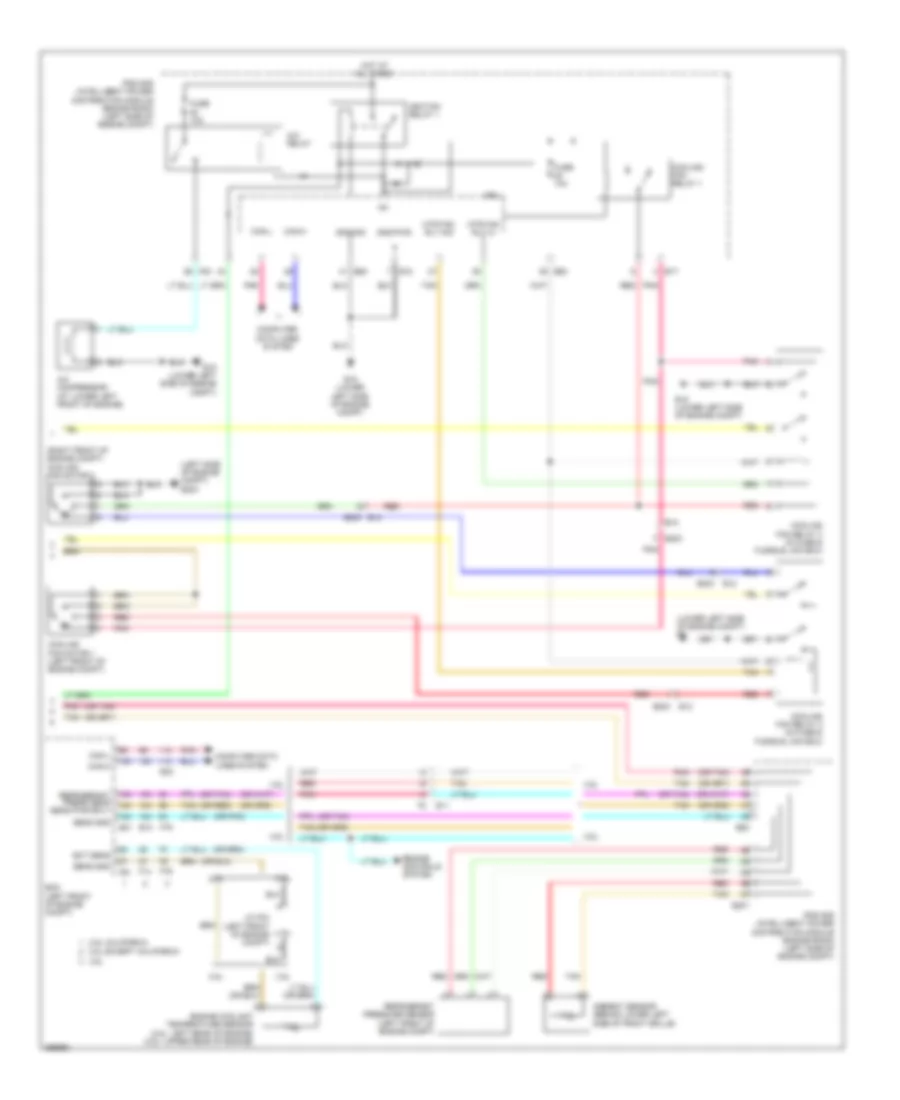
Automatic A/C Wiring Diagram, Sedan (1 of 2) for Nissan Altima SV 2013
List of elements for Automatic A/C Wiring Diagram, Sedan (1 of 2) for Nissan Altima SV 2013:
- (behind right end of dash) m61
- (or pnk)
- 13r m4
- 16p m5
- 17g
- 1m e6
- 2n m3
- 33g
- 34g
- 36g
- 3n m3
- 3r m4
- 7p m5
- A/c auto amp (center of dash)
- A/c switch assembly
- Acc rly out
- Accessory relay-2 (left end of dash)
- Actr (lin)
- Actr gnd
- Amb sens
- Ambient sensor (behind lower left side of front grille)
- Batt
- Blower motor (behind lower right side of dash)
- Body control module (bcm) (behind left side of dash)
- Can-h
- Can-l
- Can-l bwr fan rly out
- Computer data lines system
- Defogger system
- E11
- E12
- E201
- E203
- E30
- E63
- Ecv out
- F2 e11
- Fr fan pwm
- Front blower motor relay
- Fuse & fusible link box (left front of engine compt, near ipdm e/r)
- Fuse 10a
- Fuse 15a
- Fuse 5a
- Fuse block (j/b) (behind left end of dash)
- Fusible link l 40a
- Fusible link n 40a
- Gnd
- Hot at all times
- Hot in on or acc
- Hot in on or start
- Ign
- Ign usm out1
- Ign2
- In-vehicle sensor (left center of dash, near ignition switch)
- Inc sens
- Int sens
- Intake door motor (right side of blower housing)
- Intake sensor (behind right side of dash, on hvac assembly)
- Interior lights system
- Ipdm e/r (intelligent power distribution module engine room) (left side of engine compt)
- J/c e08 (left end of dash)
- Left air mix door motor (left side hvac unit)
- M1 e30
- M125
- M18
- M20
- M33
- M57 (behind left end of dash)
- M61 (behind right end of dash)
- Mode door motor (left side hvac unit)
- P gnd
- Pnk
- Red
- Right air mix door motor (right side hvac unit)
- Rr def f/b
- Rr def sw
- Rx fr
- Seats system
- Seats system computer data lines system
- Sens gnd
- Strg htr rly
- Strg htr sw
- Sun sens
- Sunload sensor (upper left side of dash, near base of windshield)
- Tan
- Tx fr
- Vactr
Automatic A/C Wiring Diagram, Sedan (2 of 2) for Nissan Altima SV 2013
List of elements for Automatic A/C Wiring Diagram, Sedan (2 of 2) for Nissan Altima SV 2013:
- (at lower left front of engine) a/c compressor
- (left side of engine compt) e204
- (lower left side of engine compt) e15
- (lower left side of engine compt) e9
- (or pnk)
- (or red)
- (or tan)
- (right front of engine compt) cooling fan motor 2
- 2.5l
- 2.5l california
- 2.5l except california
- 3.5l
- A/c relay
- Can-h
- Can-l
- Computer data lines system
- Cooling fan motor 1 (left front of engine compt)
- Cooling fan relay 1
- Cooling fan relay 2 (in fuse & fusible link box)
- Cooling fan relay 3 (in fuse & fusible link box)
- Cpu
- E10
- E11
- E12
- E15 (lower left side of engine compt)
- E17
- E18
- E201
- E203
- E203 e12
- E31
- E32
- E63
- Ecm (left front of engine compt)
- Ect sens
- Ecv
- Engine controls system
- Engine coolant temperature sensor (2.5l: left rear of engine) (3.5l: upper rear of engine)
- F14
- F79
- F83
- F88
- F91
- Fuse 10a
- Fuse 30a
- Gnd-pwr
- Gnd-sig
- Hot at all times
- Ig+
- Ignition relay 1
- Ipdm e/r (intelligent power distribution module engine room) (left side of engine compt)
- J/c f04 (left front of engine compt)
- Magnet clutch
- Mtr fan rly hi
- Mtr fan rly mid
- Pnk
- Red
- Refrigerant press sens sens pwr sply
- Refrigerant pressure sensor (left front of engine compt)
- Sens gnd
- Tan
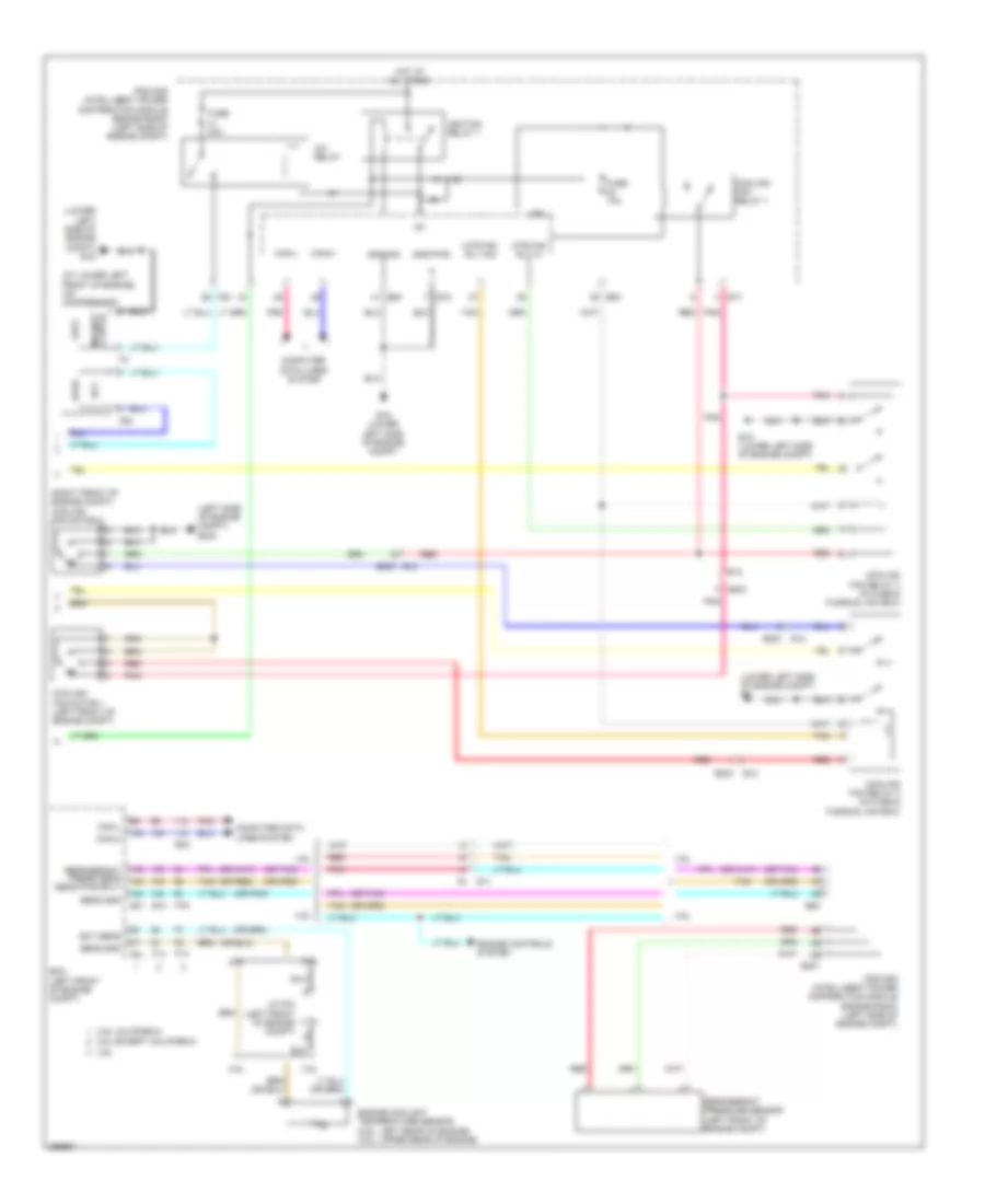
Manual A/C Wiring Diagram, Coupe (1 of 2) for Nissan Altima SV 2013
List of elements for Manual A/C Wiring Diagram, Coupe (1 of 2) for Nissan Altima SV 2013:
- 1s e7
- 23g m1
- 3n m3
- 6p e6
- 6q m4
- 7m m5
- A/c pd cut
- Air mix door motor
- Aircon sw
- Amp
- Batt
- Blower motor (behind lower right side of dash)
- Body control module (bcm) (behind left side of dash)
- Can-h
- Can-l
- Combination meter
- Comp on
- Computer data lines system
- Defogger system
- E12
- E203
- E30
- Fan on
- Fan pwm
- Front air control
- Front blower motor relay
- Fuse & fusible link box (left front of engine compt, near ipdm e/r)
- Fuse 10a
- Fuse 15a
- Fuse block (j/b) (behind left end of dash)
- Fusible link box (battery) (at battery)
- Fusible link c 100a
- Fusible link k 40a
- Fusible link m 40a
- Gnd
- Gnd (pwr)
- Hot at all times
- Hot in on or start
- Ign
- Ign2-cont
- Intake door motor (right side of blower housing)
- Interior lights system
- J/c e01 (left side of engine compt)
- Lan sig
- Light +
- Light -
- M125
- M18 bwr fan sw
- M19
- M3 2n
- M33
- M57 (behind left end of dash)
- M61 (behind right end of dash)
- Mode door motor (left side hvac unit)
- Pnk
- Rr def f/b
- Rr def on
- Vactr
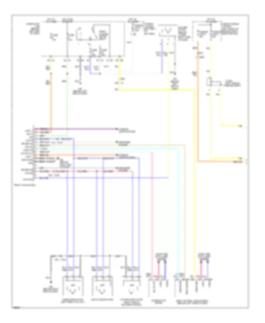
Manual A/C Wiring Diagram, Coupe (2 of 2) for Nissan Altima SV 2013
List of elements for Manual A/C Wiring Diagram, Coupe (2 of 2) for Nissan Altima SV 2013:
- (left side of engine compt) e204
- (lower left side of engine compt) e9
- (right front of engine compt) cooling fan motor 2
- A/c compressor (at lower left front of engine)
- A/c relay
- Avcc2
- Avcc2-pdpres
- California
- Can-h
- Can-l
- Computer data lines system
- Cooling fan motor 1 (left front of engine compt)
- Cooling fan relay 1
- Cooling fan relay 2 (in fuse & fusible link box)
- Cooling fan relay 3 (in fuse & fusible link box)
- Cpu
- E10
- E12
- E15 (lower left side of engine compt)
- E17
- E18
- E201
- E203
- E203 e12
- E31
- E44
- E45
- E47
- E48
- Ecm (left front of engine compt)
- Engine coolant temperature sensor (left rear of engine)
- Except california
- F1 e3
- F10
- F13
- F2 e11
- F90
- Fuse 10a
- Fuse 15a
- Gnd
- Gnda-pdres
- Gnda-tw
- Hot at all times
- Hot in on or start
- Ig+
- Ignition relay 1
- Ipdm e/r (intelligent power distribution module engine room) (left side of engine compt)
- J/c e02 (left side of engine compt)
- J/c f06 (left front of engine compt)
- J/c f07 (left side of engine compt)
- Junction block e44 & e45
- Junction block e44, e47 & e48
- Mtr fan rly hi
- Mtr fan rly mid
- P-gnd
- Pdres
- Pnk
- Red
- Refrigerant pressure sensor (left front of engine compt)
- S-gnd
- Sig
Manual A/C Wiring Diagram, Sedan (1 of 2) for Nissan Altima SV 2013
List of elements for Manual A/C Wiring Diagram, Sedan (1 of 2) for Nissan Altima SV 2013:
- (or pnk)
- (or red)
- (or tan)
- 13r m4
- 16p m5
- 33g
- 36g m1
- 3n m3
- 3r m4
- A/c pd cut
- Actr gnd
- Air mix door motor
- Amp
- Batt
- Blower motor (behind lower right side of dash)
- Body control module (bcm) (behind left side of dash)
- Bwr fan
- Bwr fan sw
- Can-h
- Can-l
- Combination meter
- Comp on
- Computer data lines system
- Defogger system
- E12
- E203
- E30
- Fan on
- Fan pwm
- Front air control
- Front blower motor relay
- Fuse & fusible link box (left front of engine compt, near ipdm e/r)
- Fuse 10a
- Fuse 15a
- Fuse 5a
- Fuse block (j/b) (behind left end of dash)
- Fusible link l 40a
- Fusible link n 40a
- Gnd
- Hot at all times
- Hot in on or start
- Ign
- Ign usm out1
- Ill+
- Ill-
- Intake door motor (right side of blower housing)
- Interior lights system
- Lin sig
- M1 34g
- M125
- M17 aircon sw
- M18
- M33
- M5 7p
- M57 (behind left end of dash)
- M61 (behind right end of dash)
- Mode door motor (left side hvac unit)
- Oat (vamb)
- Out gnd
- Pd cut
- Pnk
- Red
- Rly out
- Rr def f/b
- Rr def on
- Tan
- Vactr
Manual A/C Wiring Diagram, Sedan (2 of 2) for Nissan Altima SV 2013
List of elements for Manual A/C Wiring Diagram, Sedan (2 of 2) for Nissan Altima SV 2013:
- (left side of engine compt) e204
- (lower left side of engine compt) e9
- (or pnk)
- (or red)
- (or tan)
- (right front of engine compt) cooling fan motor 2
- 2.5l
- 2.5l california
- 2.5l except california
- 3.5l
- A/c compressor (at lower left front of engine)
- A/c relay
- Ambient sensor (behind lower left side of front grille)
- Can-h
- Can-l
- Computer data lines system
- Cooling fan motor 1 (left front of engine compt)
- Cooling fan relay 1
- Cooling fan relay 2 (in fuse & fusible link box)
- Cooling fan relay 3 (in fuse & fusible link box)
- Cpu
- E10
- E11
- E12
- E15 (lower left side of engine compt)
- E17
- E18
- E201
- E203
- E203 e12
- E31
- E32
- E63
- Ecm (left front of engine compt)
- Ect sens
- Engine controls system
- Engine coolant temperature sensor (2.5l: left rear of engine) (3.5l: upper rear of engine)
- F14
- F79
- F83
- F91
- Fuse 10a
- Gnd-pwr
- Gnd-sig
- Hot at all times
- Ig+
- Ignition relay 1
- Ipdm e/r (intelligent power distribution module engine room) (left side of engine compt)
- J/c f04 (left front of engine compt)
- Mtr fan rly hi
- Mtr fan rly mid
- Pnk
- Red
- Refrigerant press sens sens pwr sply
- Refrigerant pressure sensor (left front of engine compt)
- Sens gnd
- Tan