AIR CONDITIONING
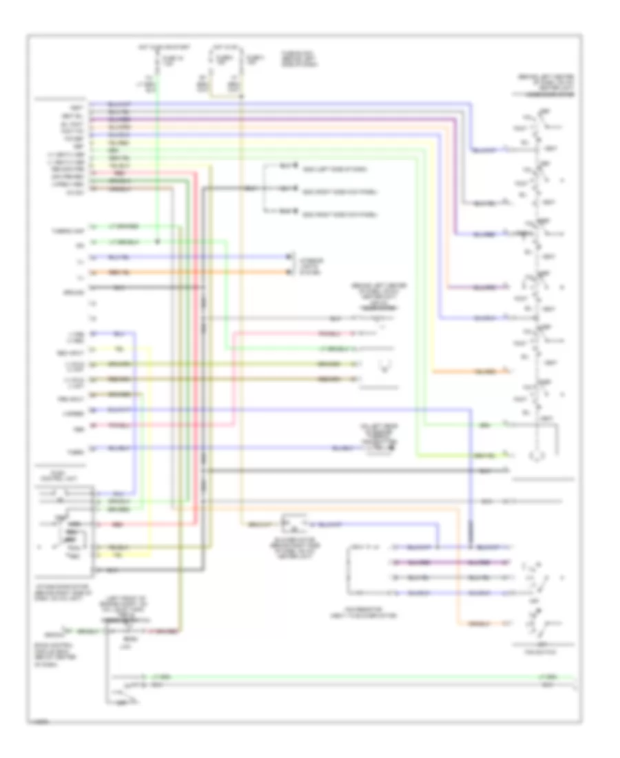
Automatic A/C Wiring Diagram (1 of 2) for Nissan Maxima GXE 1999

List of elements for Automatic A/C Wiring Diagram (1 of 2) for Nissan Maxima GXE 1999:
- "c1" fin
- (behind center
- (behind right
- (center front
- (left front of engine compt, on a/c liquid tank)
- (left side
- (on top right
- (right side kick panel)
- 11s
- 14j
- A/c auto amp (behind center of dash)
- Air mix door motor (behind left center of dash, on a/c heater unit)
- Amb sens
- Bat
- Blower motor (behind right side of dash, on a/c heater unit)
- Comp
- Fan control amp (behind glove box, on cooling unit)
- Fan f/b
- Fan gate
- Fuse 15a
- Fuse 7.5a
- Fuse block (behind left side of dash)
- G202
- G203
- Grd
- High
- Hot at all times
- Hot in on
- Ign
- Ign 2
- Ill
- In -vehicle sensor
- Incar sens
- Intake actr +
- Intake actr -
- Intake code 1
- Intake code 2
- Intake code 3
- Intake door motor (behind right side of dash, on a/c heater unit)
- Intake sens
- Interior lights system
- Lan-sig
- Light
- Low
- Mode door motor (behind left center of dash, on a/c heater unit)
- Of dash)
- Of engine compt, on radiator support) ambient sensor
- Or start
- Pnk
- Position switch
- Sense grd
- Side of dash, in defroster grille)
- Side of dash, on a/c heater unit) intake sensor
- Sun sens
- Sunload sensor
- Thermal transmitter (on left rear of engine)
- Triple pressure switch
- Vactr
- W/t sens
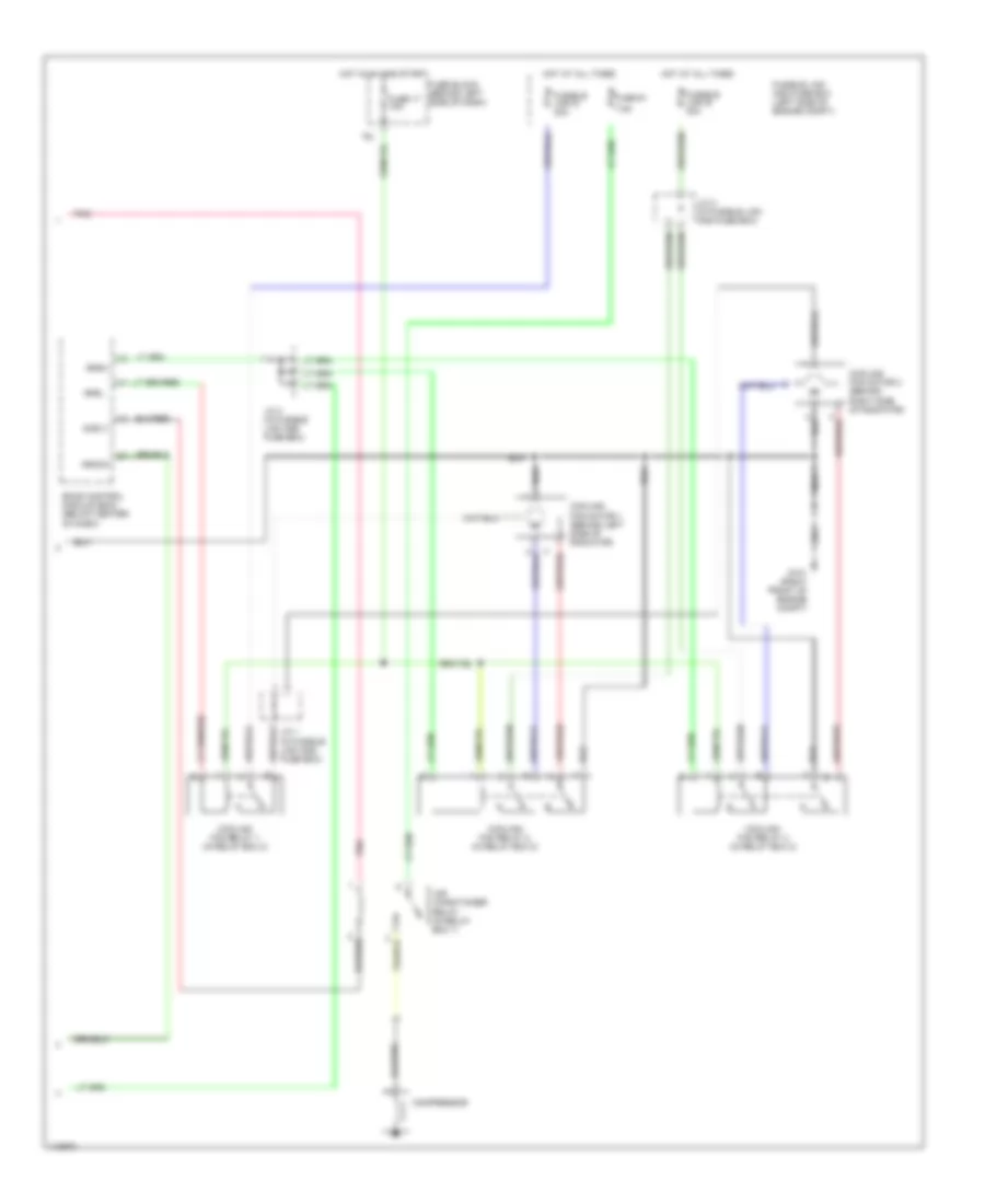
Automatic A/C Wiring Diagram (2 of 2) for Nissan Maxima GXE 1999
List of elements for Automatic A/C Wiring Diagram (2 of 2) for Nissan Maxima GXE 1999:
- 16l
- 7.5a
- Acrly
- Air conditioner relay (in relay box 1)
- Arcon
- Compressor
- Cooling fan motor 1 (behind left side of radiator)
- Cooling fan motor 2 (behind right side of radiator)
- Cooling fan relay 1 (in relay box 2)
- Cooling fan relay 2 (in relay box 2)
- Cooling fan relay 3 (in relay box 2)
- Eccs control module (ecm) (below center of dash)
- Fuse 17 10a
- Fuse 61
- Fuse block (behind left side of dash)
- Fusible link and fuse box (left side of engine compt)
- Fusible link d 30a
- Fusible link e 30a
- G101 (right front of engine compt)
- Hot at all times
- Hot in on and start
- J/c 1 (in fusible link and fuse box)
- J/c 2 (in fusible link and fuse box)
- J/c 3 (in fusible link and fuse box)
- Nca
- Pnk
- Rfrh
- Rfrl
Manual A/C Wiring Diagram (1 of 2) for Nissan Maxima GXE 1999
List of elements for Manual A/C Wiring Diagram (1 of 2) for Nissan Maxima GXE 1999:
- (+) cold (-) hot
- (+) vent/(-) def
- (+)fre/(-) rec
- (-) cold (+) hot
- (-) fre (+) rec
- (-) vent/(+) def
- (behind left center of dash, on a/c heater unit)
- (behind left center of dash, on a/c heater unit) air mix door motor
- (behind right side of dash, on a/c unit)
- (left front of engine compt, on a/c liquid tank)
- (left side of dash) g202
- (next to blower motor)
- (on left rear of engine) thermal transmitter
- (right side kick panel) g203
- 14j
- 20%
- 20% fre rec
- 4 speed
- A/c sw
- Arcon
- B/l
- B/l foot
- Blower motor (behind right side of dash, on a/c heater unit)
- Def
- Eccs control module (ecm) (below center
- F/d
- F/d def
- Fan resistor
- Fan switch
- Foot
- Foot f/d
- Fre
- Fre input
- Fuse 16 7.5a
- Fuse 2 15a
- Fuse 3 15a
- Fuse block (behind left side of dash)
- Ground
- Hot in on
- Hot in on or start
- Ign
- Ill
- Intake door motor
- Interior lights system
- Low
- Mode door motor
- Norm
- Of dash)
- Off
- Pbr
- Push control unit
- Rec
- Rec input
- Rec/20% fre
- Red
- Therm
- Thermo amp
- Triple pressure switch
- Vent
- Vent b/l
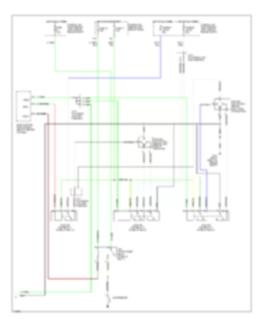
Manual A/C Wiring Diagram (2 of 2) for Nissan Maxima GXE 1999
List of elements for Manual A/C Wiring Diagram (2 of 2) for Nissan Maxima GXE 1999:
- 11s
- 16l
- Acrly
- Air conditioner relay (in relay box 1)
- Compressor
- Cooling fan motor 1 (behind left side of radiator)
- Cooling fan motor 2 (behind right side of radiator)
- Cooling fan relay 1 (in relay box 2)
- Cooling fan relay 2 (in relay box 2)
- Cooling fan relay 3 (in relay box 2)
- Eccs control module (ecm) (below center of dash)
- Fuse 7.5a
- Fuse 16 7.5a
- Fuse 17 10a
- Fuse block (behind left side of dash)
- Fusible link d 30a
- Fusible link e 30a
- Fusible link and fuse box (left side of engine compt)
- G101 (right front of engine compt)
- Hot at all times
- Hot in on and start
- J/c 1 (in fusible link and fuse box)
- J/c 2 (in fusible link and fuse box)
- J/c 3 (in fusible link and fuse box)
- Nca
- Rfrh
- Rfrl