AIR CONDITIONING
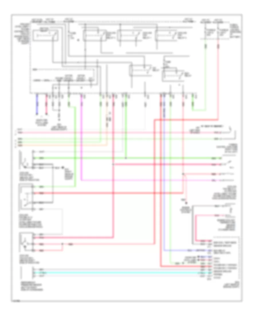
Manual A/C Wiring Diagram (1 of 2) for Nissan NV200 Taxi 2014

List of elements for Manual A/C Wiring Diagram (1 of 2) for Nissan NV200 Taxi 2014:
- 40b
- A/c compressor (lower left front of engine)
- A/c on indicator
- A/c switch
- Acc
- Air con ind output
- Air con sw
- Blower fan sw
- Blower relay
- Body control module (left end of dash)
- Can-h
- Can-l
- Computer data lines system
- Defogger system
- E11
- Fan switch
- Front air control
- Front blower motor (right side of a/c unit)
- Front blower motor resistor (lower left side of a/c unit)
- Fuse 10a
- Fuse 15a
- Fuse block j/b (lower left end of dash)
- Fusible link box (battery) (on battery positive (+) post)
- Fusible link d 60a
- Fusible link e 80a
- Hot at all times
- Hot in on or start
- Ig2
- Ignition switch
- Interior lights system
- M18
- M19
- M61 (left end of dash)
- M78
- Off
- Pnk
- Rear window defogger indicator
- Rear window defogger switch
- Red
- Start
- Thermo amp
Manual A/C Wiring Diagram (2 of 2) for Nissan NV200 Taxi 2014
List of elements for Manual A/C Wiring Diagram (2 of 2) for Nissan NV200 Taxi 2014:
- (or pnk)
- 26a
- A/c relay
- A/c rly
- Avcc2
- Can-h
- Can-l
- Computer data lines system
- Cooling fan motor 1 (behind left side of radiator)
- Cooling fan motor 2 (behind right side of radiator)
- Cooling fan relay 1
- Cooling fan relay 2
- Cooling fan relay 3
- Cooling fan relay 4 (in ipdm e/r (intelligent power power distribution module engine room))
- Cooling fan relay 5 (in ipdm e/r (intelligent power power distribution module engine room))
- Cpu
- E15 (right rear of engine compt)
- E16
- E24 (left rear of engine compt)
- E42
- E43
- E44
- E45
- E46
- E47
- E48
- E49
- Ecm (left rear of engine compt)
- Ecm relay
- Ecm relay (self shut-off)
- Eng cool temp sens
- Engine controls system
- Engine coolant temperature sensor (rear of cylinder head)
- F10
- F11
- Fuse & fusible link box (forward of battery)
- Fuse 10a
- Fuse 20a
- Fusible link f 40a
- Fusible link g 40a
- Hot at all times
- Hot in on or start
- Ignition relay
- Ipdm e/r (intelligent power distribution module engine room) (left rear of engine compt)
- M61 (left end of dash)
- M69
- Motor fan-rly driver 1
- Motor fan-rly driver 2
- Pdpres
- Pnk
- Power gnd
- Power sply for ecm
- Red
- Refrigerant pressure sensor (bottom right side of condenser)
- Sensor ground
- Thermo control amplifier (right side of a/c unit)