AIR CONDITIONING
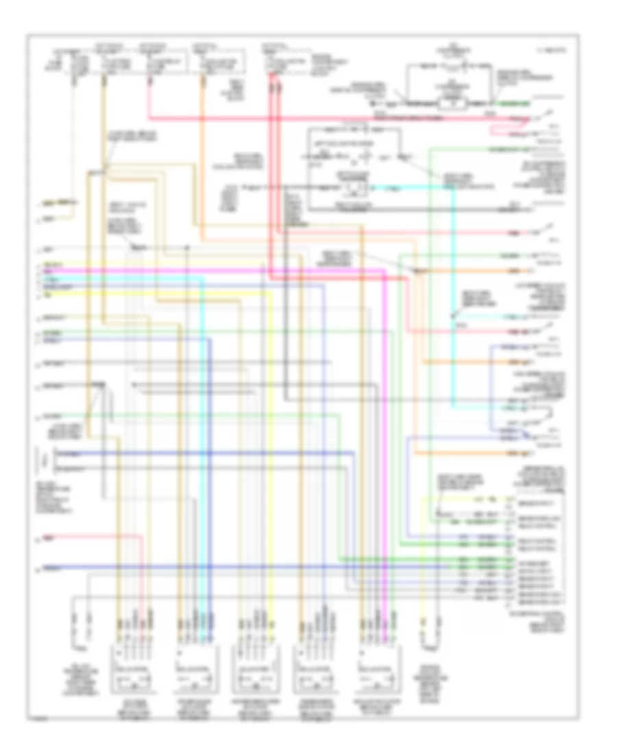
Automatic A/C Wiring Diagram (1 of 2) for Oldsmobile Aurora 1999

List of elements for Automatic A/C Wiring Diagram (1 of 2) for Oldsmobile Aurora 1999:
- (body harn, near turn flasher)
- (right kick panel)
- +5v
- A/c high pressure cut-out switch (on right front of eng compt)
- A/c low pressure cut-off switch (right side engine compartment)
- A/c req
- A10
- A11
- A12
- Act enable
- Act sense
- Amb temp input
- Ambient air temperature sensor (left front of vehicle)
- B tan
- B10
- B11
- B12
- Battery
- Blower control module (behind right side of dash)
- Blower ctrl
- Blower motor
- Blw speed feedbk
- Blw speed input
- C 1995 vftc
- C10
- C11
- C12
- C13
- C14
- C15
- C16
- Computer data lines
- D10
- D11
- D12
- D13
- D14
- D15
- D16
- Data line
- Defog rly ctrl
- Driver information center
- Flasher)
- G119 (right front of engine)
- G200 (left kick panel)
- G203
- G203 (right kick panel)
- Ground
- Heater and a/c control
- Heater and a/c programmer (behind right side of dash)
- Hot at all times
- Hvac blo mtr fuse 30a
- Hvac blower fuse 10a
- I/p 1 fuse 10a
- I/p fuse block
- Ignition
- Illumination
- Inside air temperature sensor (in dash, right of steering column)
- Inside temp input
- Interior lights system
- Left solar sensor (top left of dash)
- Lt solar sensor
- Pass ctrl gnd
- Pass ctrl input
- Passenger climate control
- Passenger heated seat module
- Pwm blw spd ctrl
- Rear defogger system
- Red
- Right rear junction block
- Right solar sensor (top right of dash)
- Rt solar sensor
- S106 (engine harn, center rear of engine compt)
- S211
- S212
- S225 (body harn, near right kick panel)
- S229 (i/p harn, behind ctr of dash)
- S231 (body harn, near turn flasher)
- S276 (hvac harn, behind right side of dash)
- S277 (hvac harn, behind right side of dash)
- S285 (body harn, near pcm)
- S288 (i/p harn, near top of dash)
- Sensor ground
- Signal status
- Tan
- Uart
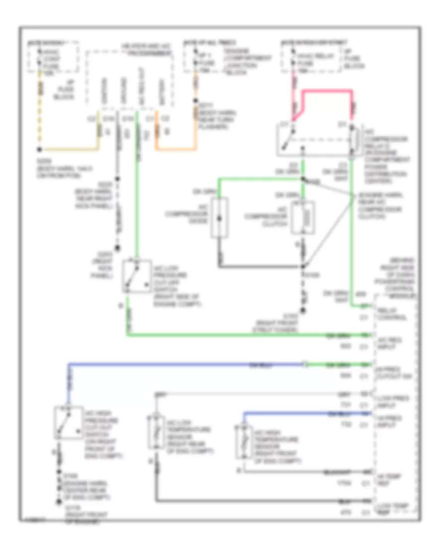
Automatic A/C Wiring Diagram (2 of 2) for Oldsmobile Aurora 1999
List of elements for Automatic A/C Wiring Diagram (2 of 2) for Oldsmobile Aurora 1999:
- (behind dash, on plenum)
- (body harn, near right cooling fan motor)
- (body harn, near right rear fender)
- (body harn, rear center of engine compartment)
- (body, 144.5 cm from pcm)
- (engine harn, near a/c compressor clutch)
- (hvac harn, behind right side of dash)
- A/c compressor clutch
- A/c compressor clutch diode
- A/c compressor control relay d (in engine compartment power distribution center)
- A/c high temperature switch (right front of engine compartment)
- A/c low temperature sensor (right rear of engine compartment)
- A/c mode actuator (behind dash, on plenum)
- A/c request
- Air inlet actuator (behind dash, on plenum)
- C 1995 vftc
- Cooling fan fuse 60a
- Cooling fan relay fuse 10a
- Driver's side actuator (behind dash, on plenum)
- Engine compartment junction block
- Engine coolant temperature sensor (top left rear of
- Engine)
- Flat pack mtr fuse 10a
- G103 (right front strut tower)
- Heater/defroster actuator (behind dash, on plenum)
- High speed cooling fan relay (in engine compt power distribution center)
- Hot at all
- Hot in run
- Hvac cont fuse 10a
- Hvac relay fuse 10a
- I/p fuse block
- Left cooling fan diode
- Left cooling fan motor
- Low speed cooling fan relay 1 (rear center of engine compartment)
- Nca
- Or start
- Passenger's side actuator
- Pnk
- Powertrain control module (behind right side of dash)
- Red
- Relay control
- Right cooling fan motor
- Right rear junction block
- S104
- S105
- S108
- S115 (body harn, right rear fender)
- S121
- S123
- S141
- S143
- S259
- S274
- S275
- S278
- Sensor ground
- Sensor input
- Series/parallel cooling fan relay (in engine compt power distribution center)
- Solid state
- Switch input
- Times
Compressor Wiring Diagram for Oldsmobile Aurora 1999
List of elements for Compressor Wiring Diagram for Oldsmobile Aurora 1999:
- (behind right side of dash) powertrain control module
- (engine harn, near a/c compressor clutch)
- A/c compressor clutch
- A/c compressor diode
- A/c compressor relay d (in engine compartment power distribution center)
- A/c high pressure cut-out switch (on right front of eng compt)
- A/c high temperature sensor (right front of eng compt)
- A/c low pressure cut-off switch (right side of engine compt)
- A/c low temperature sensor (right rear of eng compt)
- A/c req input
- A/c req out
- Battery
- D15
- D16
- Engine compartment junction block
- G103 (right front strut tower)
- G119 (right front of engine)
- G203 (right kick panel)
- Ground
- Heater and a/c programmer
- Hi pres cutout sw
- Hi pres input
- Hi temp ref
- Hot at all times
- Hot in run
- Hot in run or start
- Hvac cont fuse 10a
- Hvac relay fuse 10a
- I/p 1 fuse 10a
- I/p fuse block
- Ignition
- Low pres input
- Low temp ref
- Pnk
- Relay control
- S105
- S106 (engine harn, center rear of eng compt)
- S108
- S211 (body harn, near turn flasher)
- S259 (body harn, 144.5 cm from pcm)