AIR CONDITIONING
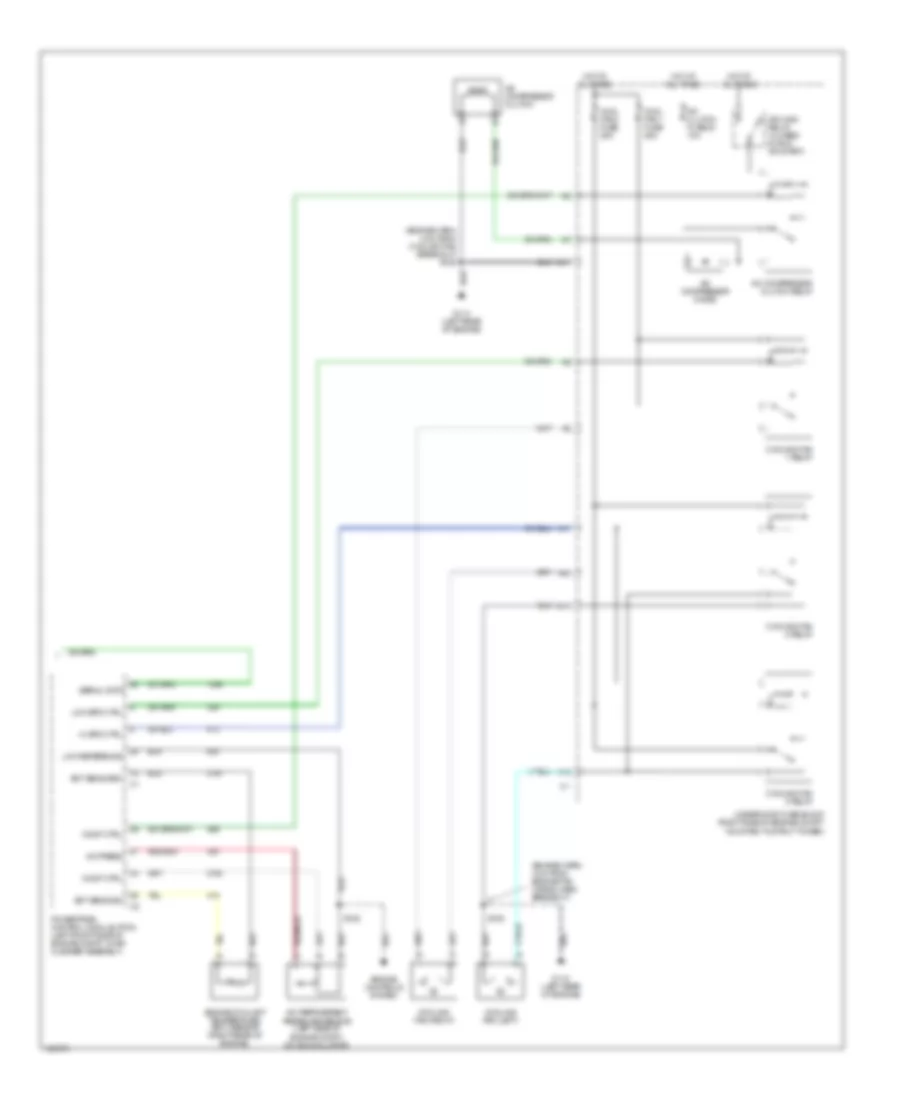
Automatic A/C Wiring Diagram (1 of 2) for Oldsmobile Intrigue GL 2000

List of elements for Automatic A/C Wiring Diagram (1 of 2) for Oldsmobile Intrigue GL 2000:
- (dash harn, 2 cm from radio antenna breakout)
- (dash harn, 2 cm from radio harn breakout)
- (dash harn, 4 cm from radio breakout)
- (right side of dash) g201
- (right side of steering column) sp205
- +5 v
- A/c sol ctrl
- A/c solenoid
- Ambient outside temperature sensor (behind front fasia, mounted to radiator air baffle)
- Battery
- Bi-lev sol ctrl
- Bi-level solenoid
- Blower motor
- Blower motor control module (under right side of dash, in right side of heater-a/c module)
- C10
- C11
- C12
- C13
- C14
- C15
- C16
- Cntrl in
- D10
- D11
- D12
- D13
- D14
- D15
- D16
- Data link connector (under left side of dash, right of steering column)
- Def sol ctrl
- Defrost solenoid
- Fuse block (behind right side of dash)
- Grd
- Ground
- Heater solenoid
- High blower fuse 30a
- Hot at all times
- Hot in run
- Htr sol ctrl
- Hvac control assembly
- Hvac fuse 10a
- Ignition
- Illuminating
- Inside air temperature sensor (behind dash, between the radio & knee bolster)
- Inside temp input
- Interior lights system
- Left air temperature actutor (left side of hvac module)
- Lt elec actuator
- Motor drive
- Nca
- Outside temp input
- Radio-hvac fuse 15a
- Recirc sol ctrl
- Recirc solenoid
- Red
- Right air temperature actutor (right side of hvac module)
- Rt elec actuator
- S202 (dash harn, 8 cm from data link breakout)
- S230
- S231
- S233
- S258
- Sensor ground
- Serial data
- Solid state
- Spd cntrl
- Sun load input
- Sun load temperature sensor (top left of dash)
- Tan
- Vacuum control assembly (on right side of hvac module)
- Volt to blw ctrl
Automatic A/C Wiring Diagram (2 of 2) for Oldsmobile Intrigue GL 2000
List of elements for Automatic A/C Wiring Diagram (2 of 2) for Oldsmobile Intrigue GL 2000:
- (engine harn, 4 cm from coolant fan breakout) s105
- (engine harn, 4 cm from engine fan wiring harn breakout)
- A/c compressor clutch
- A/c clutch fuse 23 10a
- A/c compressor clutch relay
- A/c compressor diode
- A/c press
- A/c refrigerent pressure sensor (left side of engine compt, on accumulator)
- A10
- A11
- C11
- Comp ctrl
- Cool fan 1 fuse 25a
- Cool fan 2 fuse 25a
- Cooling fan (left)
- Cooling fan (right)
- Cooling fan 1 relay
- Cooling fan 2 relay
- Cooling fan 3 relay
- Ect sens grd
- Ect sens sig
- Engine controls system
- Engine coolant temperature (ect) sensor (right rear of engine)
- F12
- G114 (left rear of engine)
- Hi spd ctrl
- Hot at all times
- Ign main relay (closed in run or start)
- Low reference
- Low spd ctrl
- Powertrain control module (pcm) (left front side of engine compt, in air cleaner assembly)
- S105
- S128
- Serial data
- Underhood fuse block (right side of engine compt, mounted to strut tower)
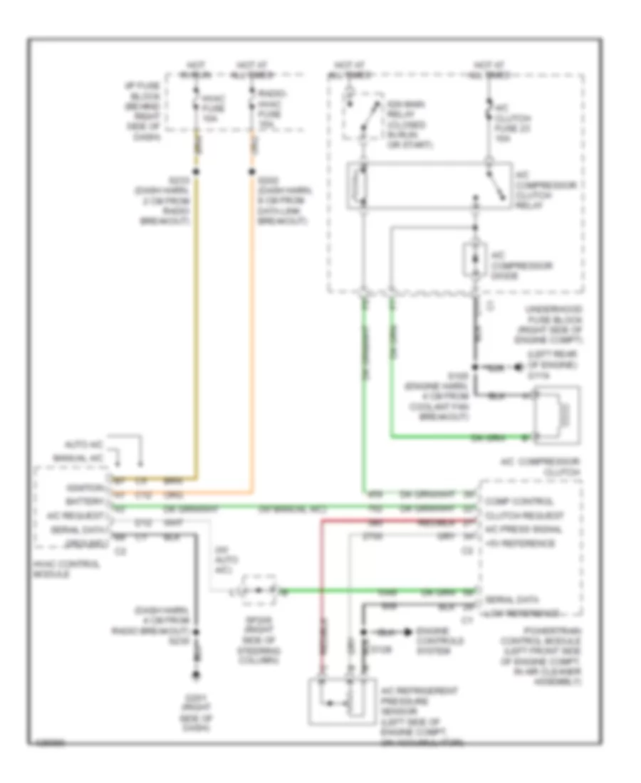
Compressor Wiring Diagram for Oldsmobile Intrigue GL 2000
List of elements for Compressor Wiring Diagram for Oldsmobile Intrigue GL 2000:
- (dash harn, 4 cm from radio breakout) s230
- (left rear of engine) g114
- (w/ auto a/c)
- (w/ manual a/c)
- +5v reference
- A/c compressor clutch
- A/c clutch fuse 23 10a
- A/c compressor clutch relay
- A/c compressor diode
- A/c press signal
- A/c refrigerent pressure sensor (left side of engine compt, on accumulator)
- A/c request
- Auto a/c
- Battery
- C11
- C12
- Clutch request
- Comp control
- D12
- Engine controls system
- G201 (right side of dash)
- Ground
- Hot at all times
- Hot in run
- Hvac control module
- Hvac fuse 10a
- I/p fuse block (behind right side of dash)
- Ign main relay (closed in run or start)
- Ignition
- Low reference
- Manual a/c
- Powertrain control module (left front side of engine compt, in air cleaner assembly)
- Radio- hvac fuse 15a
- S105 (engine harn, 4 cm from coolant fan breakout)
- S128
- S202 (dash harn, 8 cm from data link breakout)
- S233 (dash harn, 2 cm from radio breakout)
- Serail data
- Serial data
- Sp205 (right side of steering column)
- Underhood fuse block (right side of engine compt)
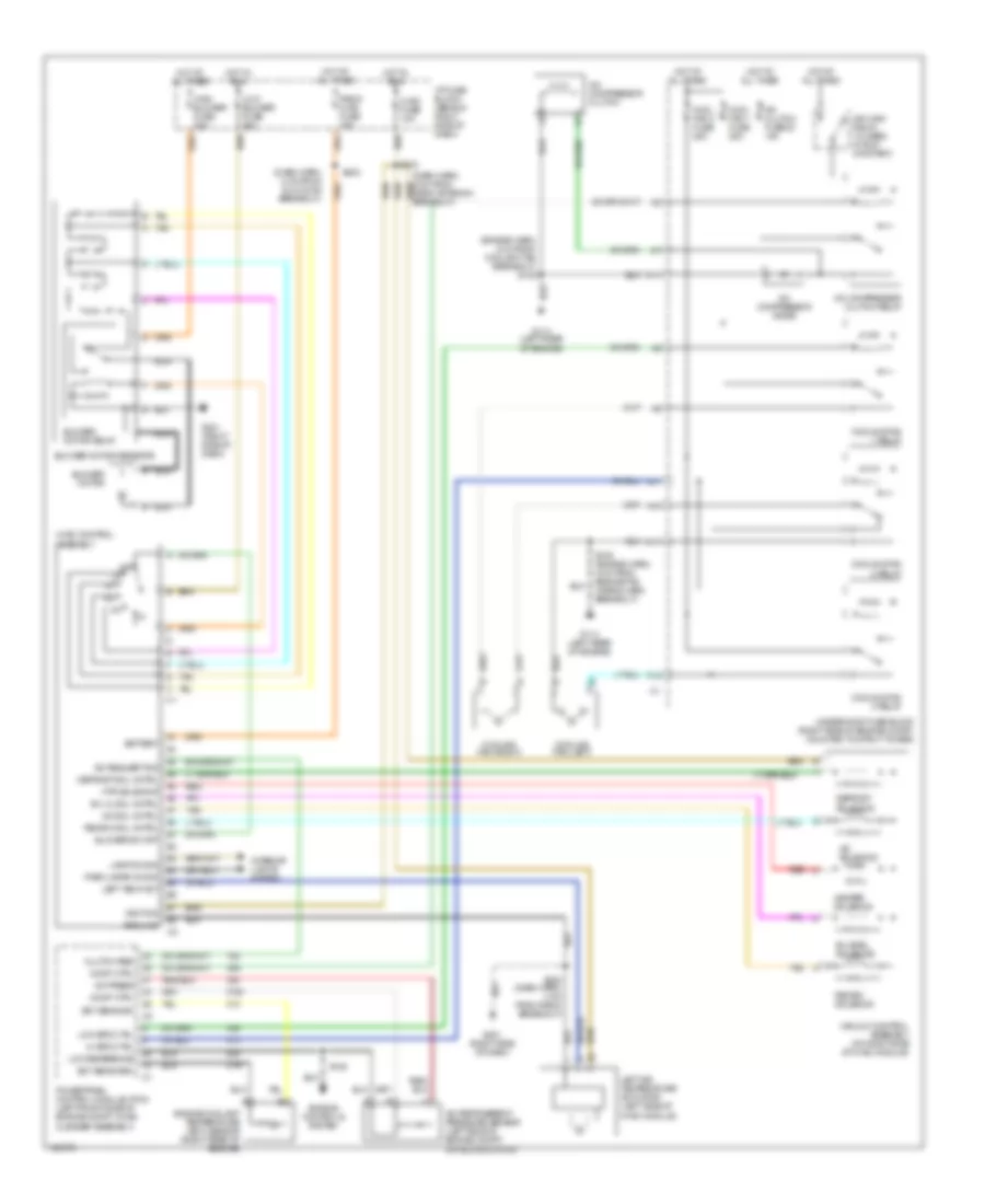
Manual A/C Wiring Diagram for Oldsmobile Intrigue GL 2000
List of elements for Manual A/C Wiring Diagram for Oldsmobile Intrigue GL 2000:
- (dash harn, 8 cm from dlc conn breakout)
- (engine harn, 4 cm from coolant fan breakout) s105
- A/c compressor clutch
- A/c clutch fuse 23 10a
- A/c compressor clutch relay
- A/c compressor diode
- A/c press
- A/c refrigerent pressure sensor (left side of engine compt, on accumulator)
- A/c request sig
- A/c sol cntrl
- A/c solenoid
- A10
- A11
- Battery
- Bi-level solenoid
- Bi-lvl sol cntrl
- Blower motor
- Blower motor relay
- Blower motor resistor
- Blower sw off
- C11
- Clutch req
- Comp ctrl
- Cool fan 1 fuse 25a
- Cool fan 2 fuse 25a
- Cooling fan (left)
- Cooling fan (right)
- Cooling fan 1 relay
- Cooling fan 2 relay
- Cooling fan 3 relay
- Defrost sol cntrl
- Defrost solenoid
- Ect sens grd
- Ect sens sig
- Engine controls system
- Engine coolant temperature (ect) sensor (right rear of engine)
- F12
- G114 (left rear of engine)
- G201 (right side of dash)
- Ground
- Heater solenoid
- Hi spd ctrl
- High blower fuse 30a
- Hot at all times
- Hot in run
- Htr solenoid
- Hvac control assembly
- Hvac fuse 10a
- I/p fuse block (behind right side of dash)
- Ign main relay (closed in run or start)
- Ignition
- Interior lights system
- Lamp dim sig
- Left air temperature actuator (left side of hvac module)
- Left temp act
- Low blower fuse 20a
- Low reference
- Low spd ctrl
- Nca
- Off
- Park lamps on sig
- Powertrain control module (pcm) (left front side of engine compt, in air cleaner assembly)
- Radio hvac fuse 15a
- Recirc sol cntrl
- Recirc solenoid
- Red
- S105 (engine harn, 4 cm from engine fan wiring harn breakout)
- S128
- S202
- S230 (dash harn, 4 cm from radio breakout)
- S233
- Tan
- Underhood fuse block (right side of engine compt, mounted to strut tower)
- Vacuum control assembly (on right side of hvac module)