AIR CONDITIONING
3.1L
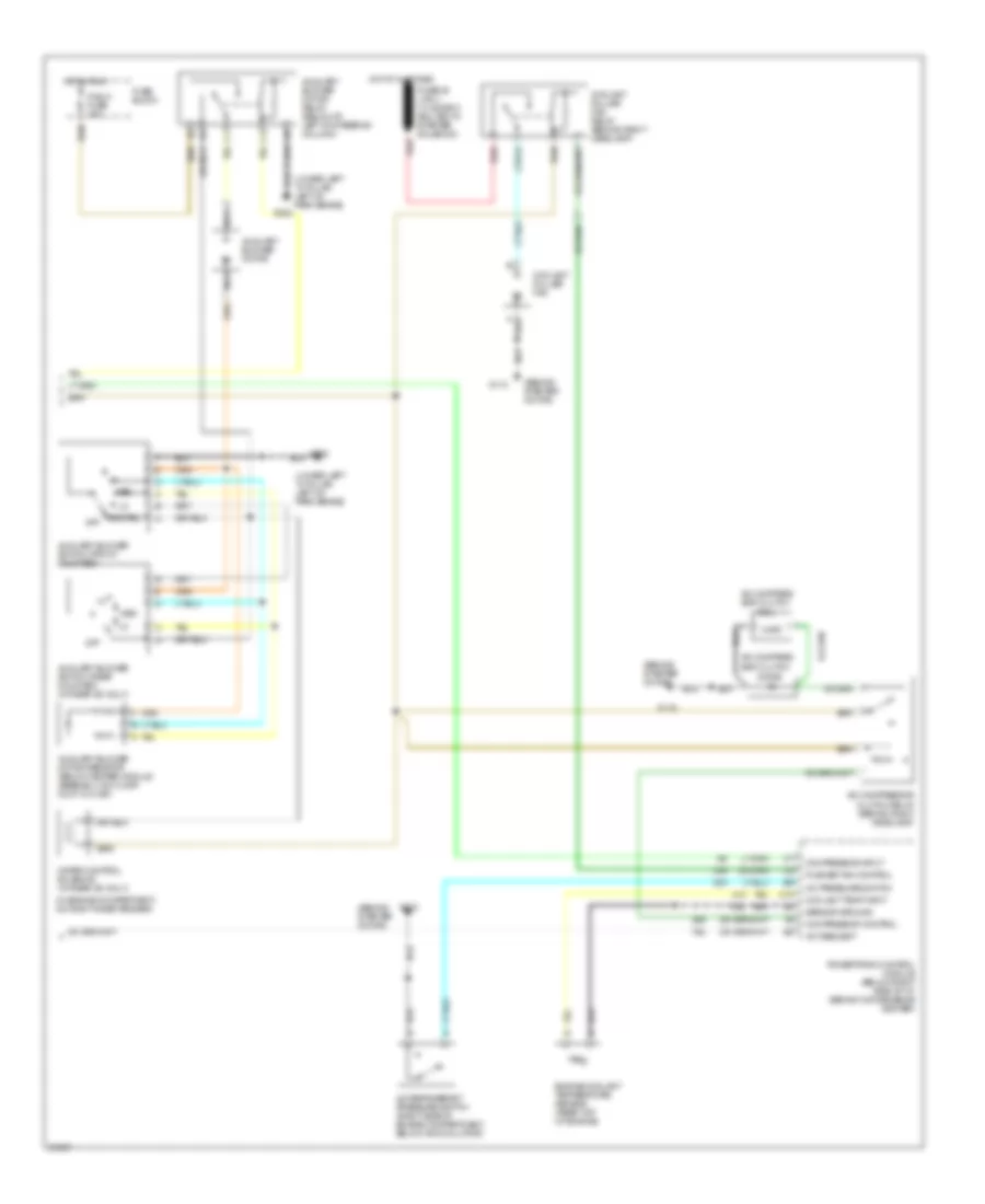
3.1L (VIN D), A/C Wiring Diagram (1 of 2) for Oldsmobile Silhouette 1995

List of elements for 3.1L (VIN D), A/C Wiring Diagram (1 of 2) for Oldsmobile Silhouette 1995:
- (mounted to heater and a/c module assembly)
- A/c compressor high pressure cut-off switch (back of a/c compressor)
- A/c compressor low pressure cut-off switch (back of a/c compressor)
- A/c switch
- B-lv
- Blower motor
- Blower motor relay, high speed
- Blower motor relay, low speed (in convenience center)
- Blower motor resistor (mounted to heater and a/c module assembly)
- Blower switch
- Defrost
- Fuse block
- G202 (lower left "a" pillar, left of park brake)
- Heater and a/c control assembly
- Hot at all times
- Hot in run
- Htr-a/c fuse 25a
- Ign fuse 15a
- Interior lights system
- Lower
- Mix(defog)
- Nca
- Off
- Rdo1/aux fuse 20a
- Rear defogger indicator
- Rear defogger switch
- Rear defogger system
- Recirc
- Red
- Solenoid 1
- Solenoid 2
- Solenoid 3
- Solenoid 4
- Solenoid 5
- Solenoid box (below i/p, on right side of heater and a/c module assembly)
- Solid state
- Tan
- Temperature door actuator (top right side of heater and a/c module assembly)
- Upper
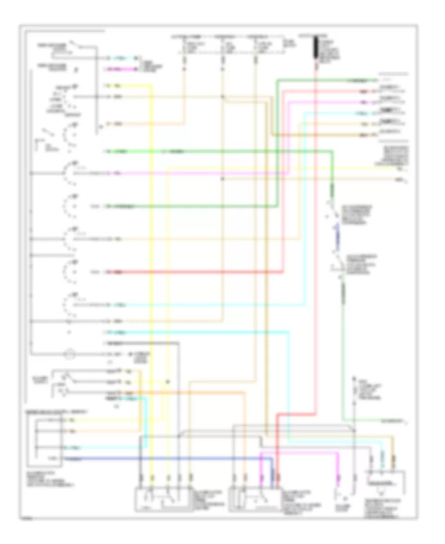
3.1L (VIN D), A/C Wiring Diagram (2 of 2) for Oldsmobile Silhouette 1995
List of elements for 3.1L (VIN D), A/C Wiring Diagram (2 of 2) for Oldsmobile Silhouette 1995:
- (behind starter motor)
- (in engine compartment, on right inner fender)
- (lower left "a" pillar, left of park brake)
- A/c compres- sor clutch
- A/c compressor clutch relay (behind right headlamp)
- A/c pressure switch
- A/c refrigerant pressure switch (right side of engine compartment, below accumulator)
- A/c request
- Auxiliary blower motor
- Auxiliary blower motor relay (below i/p, left of steering column)
- Auxiliary blower motor resistor (below heater module assembly, on floor duct outlet)
- Auxiliary blower switch (front mounted)
- Auxiliary blower switch (rear mounted) (w/ rear a/c only)
- C10
- Coil
- Compressor control
- Compressor input
- Coolant puller fan
- Coolant puller fan relay (behind right headlamp)
- Coolant temp input
- Diode
- Engine coolant temperature sensor (rear top of engine)
- Fuse block
- G112
- G202
- Hot at all times
- Hot in run
- Med
- Nca
- Off
- Powertrain control module (below right side of i/p, behind convenience center)
- Pusher fan control
- R blw fuse 25a
- Red
- Rr ctrl
- Sensor ground
- Water control solenoid (w/ rear a/c only)
Heater Wiring Diagram for Oldsmobile Silhouette 1995
List of elements for Heater Wiring Diagram for Oldsmobile Silhouette 1995:
- (lower left "a" pillar, left of park brake)
- (mounted to heater and a/c module assembly)
- (not used)
- Auxiliary blower motor
- Auxiliary blower motor relay (below i/p, left of steering column)
- Auxiliary blower motor resistor (below heater module assembly, on floor duct outlet)
- Auxiliary blower switch (front mounted)
- B-lv
- Blower motor
- Blower motor relay, high speed
- Blower motor relay, low speed (in convenience center)
- Blower motor resistor (mounted to heater and a/c module assembly)
- Blower switch
- C 1995 vftc
- Defrost
- Fuse block
- G202
- G202 (lower left "a" pillar, left of park brake)
- Heater and a/c control assembly
- Hot at all times
- Hot in run
- Htr-a/c fuse 25a
- Ign fuse 15a
- Interior lights system
- Lower
- Med
- Mix(defog)
- Nca
- Not used
- Off
- R blw fuse 25a
- Rdo1/aux fuse 20a
- Rear defogger indicator
- Rear defogger switch
- Rear defogger system
- Red
- Solenoid 1
- Solenoid 2
- Solenoid 3
- Solenoid 5
- Solenoid box (below i/p, on right side of heater and a/c module assembly)
- Solid state
- Tan
- Temperature door actuator (top right side of heater and a/c module assembly)
- Upper
3.8L
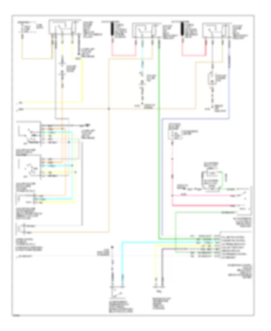
3.8L (VIN L), A/C Wiring Diagram (1 of 2) for Oldsmobile Silhouette 1995
List of elements for 3.8L (VIN L), A/C Wiring Diagram (1 of 2) for Oldsmobile Silhouette 1995:
- (mounted to heater and a/c module assembly)
- A/c compressor high pressure cut-off switch (back of a/c compressor)
- A/c compressor pressure cycling switch (on side of evaporator)
- A/c switch
- B-lv
- Blower motor
- Blower motor relay, high speed
- Blower motor relay, low speed (in convenience center)
- Blower motor resistor (mounted to heater and a/c module assembly)
- Blower switch
- Defrost
- Fuse block
- G202 (lower left "a" pillar, left of park brake)
- Heater and a/c control assembly
- Hot at all times
- Hot in run
- Htr-a/c fuse 25a
- Ign fuse 15a
- Interior lights system
- Lower
- Mix(defog)
- Nca
- Off
- Rdo1/aux fuse 20a
- Rear defogger indicator
- Rear defogger switch
- Rear defogger system
- Recirc
- Red
- Solenoid 1
- Solenoid 2
- Solenoid 3
- Solenoid 4
- Solenoid 5
- Solenoid box (below i/p, on right side of heater and a/c module assembly)
- Solid state
- Tan
- Temperature door actuator (top right side of heater and a/c module assembly)
- Upper
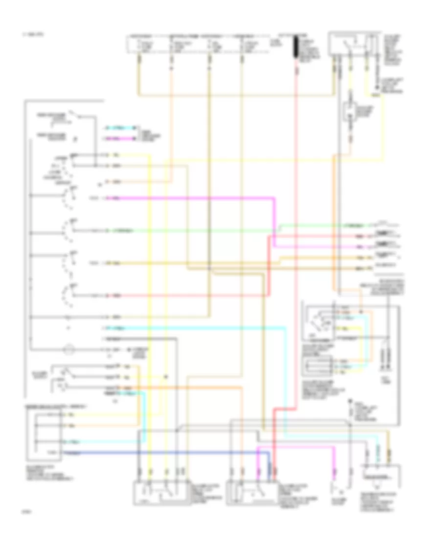
3.8L (VIN L), A/C Wiring Diagram (2 of 2) for Oldsmobile Silhouette 1995
List of elements for 3.8L (VIN L), A/C Wiring Diagram (2 of 2) for Oldsmobile Silhouette 1995:
- (behind left headlamp)
- (front of engine)
- (in engine compartment, on right inner fender)
- (lower left "a" pillar, left of park brake)
- A/c compres- sor clutch
- A/c compressor clutch relay (behind right headlamp)
- A/c pressure switch
- A/c refrigerant pressure switch (right side of engine compartment, below accumulator)
- A/c request
- Auxiliary blower motor
- Auxiliary blower motor relay (below i/p, left of steering column)
- Auxiliary blower motor resistor (below heater module assembly, on floor duct outlet)
- Auxiliary blower switch (front mounted)
- Auxiliary blower switch (rear mounted) (w/ rear a/c only)
- C16
- Coil
- Compressor control
- Convenience center
- Coolant puller fan
- Coolant puller fan relay (behind right headlamp)
- Coolant pusher fan
- Coolant pusher fan relay (behind right headlamp)
- Coolant temp input
- D10
- D11
- D12
- Diode
- Engine coolant temperature sensor (rear top of engine)
- F13
- Fuse block
- G106
- G120 (right side of engine)
- G125
- G202
- Hot at all times
- Hot in run
- Hot in run, bulb test or start
- Ign fuse 15a
- Med
- Nca
- Off
- Pnk
- Powertrain control module (below right side of i/p, behind convenience center)
- Puller fan control
- Pusher fan control
- R blw fuse 25a
- Red
- Rr ctrl
- Sensor ground
- Water control solenoid (w/ rear a/c only)
Heater Wiring Diagram for Oldsmobile Silhouette 1995
List of elements for Heater Wiring Diagram for Oldsmobile Silhouette 1995:
- (lower left "a" pillar, left of park brake)
- (mounted to heater and a/c module assembly)
- (not used)
- Auxiliary blower motor
- Auxiliary blower motor relay (below i/p, left of steering column)
- Auxiliary blower motor resistor (below heater module assembly, on floor duct outlet)
- Auxiliary blower switch (front mounted)
- B-lv
- Blower motor
- Blower motor relay, high speed
- Blower motor relay, low speed (in convenience center)
- Blower motor resistor (mounted to heater and a/c module assembly)
- Blower switch
- C 1995 vftc
- Defrost
- Fuse block
- G202
- G202 (lower left "a" pillar, left of park brake)
- Heater and a/c control assembly
- Hot at all times
- Hot in run
- Htr-a/c fuse 25a
- Ign fuse 15a
- Interior lights system
- Lower
- Med
- Mix(defog)
- Nca
- Not used
- Off
- R blw fuse 25a
- Rdo1/aux fuse 20a
- Rear defogger indicator
- Rear defogger switch
- Rear defogger system
- Red
- Solenoid 1
- Solenoid 2
- Solenoid 3
- Solenoid 5
- Solenoid box (below i/p, on right side of heater and a/c module assembly)
- Solid state
- Tan
- Temperature door actuator (top right side of heater and a/c module assembly)
- Upper