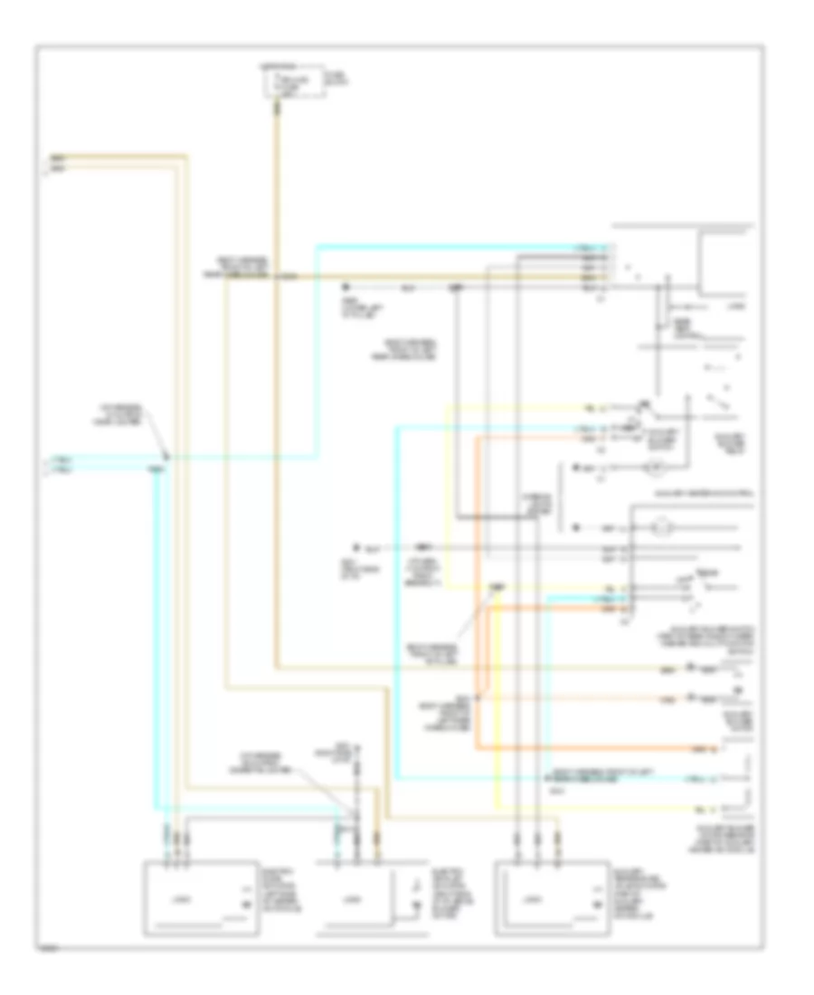
AIR CONDITIONING
A/C Wiring Diagram (1 of 2) for Oldsmobile Silhouette GLS 1998

List of elements for A/C Wiring Diagram (1 of 2) for Oldsmobile Silhouette GLS 1998:
- (eng harn, 15 cm from pcm breakout)
- (eng harn, 5 cm from pcm breakout)
- (i/p harn, 16 cm from relay center breakout)
- (i/p harness, 68 cm from cigarette lighter)
- 5 volts ref
- A/c clu diode
- A/c clu fuse 10a
- A/c clu relay
- A/c compressor clutch coil
- A/c refrigerant pressure sensor (on left side of engine compt, below accumulator)
- A/c req sig
- A/c switch
- A10
- Air recirc
- Air source logic
- Blower motor
- Blower motor relay
- Blower motor resistor (behind left side of dash)
- Blower motor resistors
- C1 a
- C10
- C11
- Compressor request logic
- Cool fan 1 maxi fuse 30a
- Cool fan 1 relay
- Cool fan 2 maxi fuse 30a
- Cool fan 2 relay
- Cool fan relay
- Defog switch
- Defogger logic
- Defogger system
- Defrost/ defog
- Engine controls system
- Engine coolant fan motor 1
- Engine coolant fan motor 2
- F11
- Frt hvac hi blwr fuse 30a
- Frt hvac low/ med blwr fuse 25a
- Fuse block
- G125 (lower front of engine)
- G201 (right side of dash)
- Heater-a/c control
- Hi spd fan ctrl
- Hot at all times
- Hot in run
- Hot in run, bulb test or start
- Hvac/ drl fuse 10a
- Illumination
- Lo spd fan ctrl
- Nca
- Off
- Powertrain control module (engine compt, in air cleaner assembly)
- Radio fuse 10a
- Relay ctrl
- S105 (engine harn, 13 cm from breakout to coolant fan 1)
- S202 (i/p harness, 21 cm from radio breakout)
- S213
- S264
- Sensor ground
- Sensor signal
- Tan
- Temp control
- Underhood junction block
A/C Wiring Diagram (2 of 2) for Oldsmobile Silhouette GLS 1998
List of elements for A/C Wiring Diagram (2 of 2) for Oldsmobile Silhouette GLS 1998:
- (body harness, front of left "b" pillar)
- (body harness, front of left rear wheelhouse)
- (i/p harn, 4 cm from radio breakout)
- (i/p harness, 68 cm from cigarette lighter)
- (i/p harness, 72 cm from cigar lighter)
- Auxiliary blower motor
- Auxiliary blower motor resistor (part of auxiliary heater-a/c module)
- Auxiliary blower relay
- Auxiliary blower switch
- Auxiliary blower switch (part of rear window wiper/ washer and multi-function switch)
- Auxiliary heater-a/c control
- Auxiliary temperature valve actuator (part of auxiliary heater- a/c module)
- Electric air inlet actuator (right side of i/p, above blower motor)
- Electric slave actuator (left side of heater- a/c module)
- Fuse block
- G201 (right side of i/p)
- G999 (lower left "d" pillar)
- Hot in run
- Interior lights system
- Logic
- Med
- Nca
- Off
- Rear
- Rear temp control
- Rr hvac fuse 25a
- S213
- S230
- S252
- S339
- S341
- S343 (body harness, front of left rear wheelhouse)
- S345
- S403
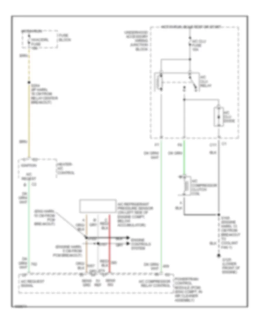
Compressor Wiring Diagram for Oldsmobile Silhouette GLS 1998
List of elements for Compressor Wiring Diagram for Oldsmobile Silhouette GLS 1998:
- (eng harn, 15 cm from pcm breakout)
- (engine harn, 5 cm from pcm breakout)
- 5v ref
- A/c clu diode
- A/c clu fuse 10a
- A/c clu relay
- A/c compressor clutch coil
- A/c compressor relay control
- A/c refrigerant pressure sensor (on left side of engine compt, below accumulator)
- A/c reqest
- A/c request signal
- C11
- Engine controls system
- Fan 1)
- Fuse block
- G125 (lower front of engine)
- Heater- a/c control
- Hot in run
- Hot in run, bulb test or start
- Hvac/drl fuse 10a
- Ignition
- Powertrain control module (pcm) (eng compt, in air cleaner assembly)
- S122
- S167
- S264 (i/p harn, 16 cm from relay center breakout)
- Sens grd
- Sens sig
- Underhood accessory wiring junction block