AIR CONDITIONING
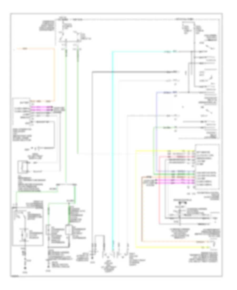
Automatic A/C Wiring Diagram (1 of 2) for Pontiac Bonneville GXP 2005

List of elements for Automatic A/C Wiring Diagram (1 of 2) for Pontiac Bonneville GXP 2005:
- (2 cm from instrument cluster breakout)
- (23.5 cm from c204 breakout)
- (in hvac harn, 30 cm from c204 breakout) s221
- (in hvac harness, 36.5 cm from c204 breakout)
- (in i/p harness, 35 cm from instrument cluster breakout)
- (mounted on right front of blower motor) blower motor control processor
- 5v ref
- A10
- A11
- A12
- Amb air temp sig
- Amb light sens
- Ambient air temperature sensor (center of engine compt, forward of radiator)
- Backlight
- Bat pos volt
- Battery
- Blower motor (under right side of dash, above sound insulator)
- Blwr mtr gnd
- Blwr sp cntrl
- Blwr volt
- C1 a1
- C11
- C12
- C13
- C3 e11
- Class 2 serial
- Clock sig
- Computer data lines system
- D11
- D12
- D16
- Data sig
- Dim fuse 38 10a
- Drvr sun ld sens
- G200
- G201
- Gnd
- Ground
- Headlights system
- Hot at all times
- Hot in on
- Hvac batt fuse 37 10a
- Hvac blo fuse 2 30a
- Hvac control module (in center of dash)
- Hvac fuse 33 10a
- Ign 3 rr fuse 34 10a
- Ign 3 volt
- Ign 3 voltage
- In air temp sig
- Inside air temperature sensor (on dash, right of steering column)
- Instrument panel integration module (behind left side of dash)
- Interior lights system
- Left air temp dr
- Left air temperature actuator (on top left side of hvac assembly)
- Lft air temp dr
- Low left temp sig
- Low ref
- Low rt temp sig
- Lower left air temperature sensor (behind left air discharge vent)
- Lower right air temperature sensor (behind right air discharge vent)
- Mode actuator (under left side of dash, on left side of hvac assembly)
- Mode dr ctrl
- Mode dr pos sens
- Mtr ctrl
- Mtr spd ctrl
- Nca
- Pass sun ld sens
- Rear fuse block (under left rear seat)
- Recirc dr ctrl
- Recirc dr pos
- Recirculation actuator (right side of dash, right of blower motor)
- Right air temp dr
- Right air temperature actuator (behind glove box, on right side of hvac assembly)
- Rt air temp dr
- S203 (in i/p harness, 6.5 cm from ipm breakout)
- S204
- S205
- S222
- S253 (in i/p wiring harness, 13 cm from turn signal hazard flasher module)
- Solid state
- Sp200 (left front door pillar)
- Sp201 (on right front door pillar)
- Sp201 (right front door pillar)
- Sunload sensor assembly (on top center of dash)
- Tan
- Up left temp sig
- Up rt temp sig
- Upper left air temperature sensor (behind left air discharge vent)
- Upper right air temperature sensor (behind right air discharge vent)
Automatic A/C Wiring Diagram (2 of 2) for Pontiac Bonneville GXP 2005
List of elements for Automatic A/C Wiring Diagram (2 of 2) for Pontiac Bonneville GXP 2005:
- ( in engine harness, 6.5 cm from idle air control valve connector breakout)
- (front of a/c compressor) a/c compressor clutch
- (high speed) coolfan 2 relay 37
- (in engine harness, 9.5 cm from pcm connector) s105
- 3.8l
- 3.8l 4.6l
- 4.6l
- 474 (or 2700)
- 5v ref
- 808 (or 2751)
- A/c clu fuse 26 15a
- A/c clu relay 32
- A/c compressor clutch (on front of a/c compressor)
- A/c compressor clutch diode (on wiring harness, near a/c compressor)
- A/c compressor clutch solenoid
- A/c compressor temperature switch
- A/c refrigerant low temperature sensor (4.6l) (rear center of engine, on high pressure line junction block to evaporator core)
- A/c refrigerant pressure sensor (behind a/c compressor, on a/c line)
- A10
- A11
- A11 class 2 serial a12 class 2 serial a6
- A12
- B10
- B11
- Battery
- C10
- C11
- Class 2 serial
- Clutch rly ctrl
- Computer data lines system
- Cool fan 1 fuse 47 30a
- Cool fan 2 fuse 46 30a
- Coolfan 1 relay (low speed)
- Coolfan s/p relay 39 (series/parallel)
- D10
- Dash integration module (dim) (4.6l) (behind right side of dash, under sound insulator)
- E10
- E11
- Ect sens sig
- Engine controls system
- Engine coolant temperature (ect) sensor (3.8l: on rear of engine, near thermostat housing) (4.6l: below throttle body)
- F11
- G10
- G103
- G105
- G108
- G11
- G200
- Gnd
- High spd fan cntrl
- Hot at all times
- Hot in on
- Left cooling fan (at left front of engine compt)
- Lo ref
- Low ref
- Low spd fan cntrl
- Nca
- Powertrain control module (in air cleaner housing)
- Right cooling fan (at right front of engine compt)
- S106
- S109
- S130
- Sens sig
- Sensor signal
- Sp103 (in front of underhood fuse block)
- Sp105 (below ignition control module)
- Sp200 (on left front door pillar)
- T10
- T11
- Underhood fuse block (right front side of engine compartment)
- V10
- V11
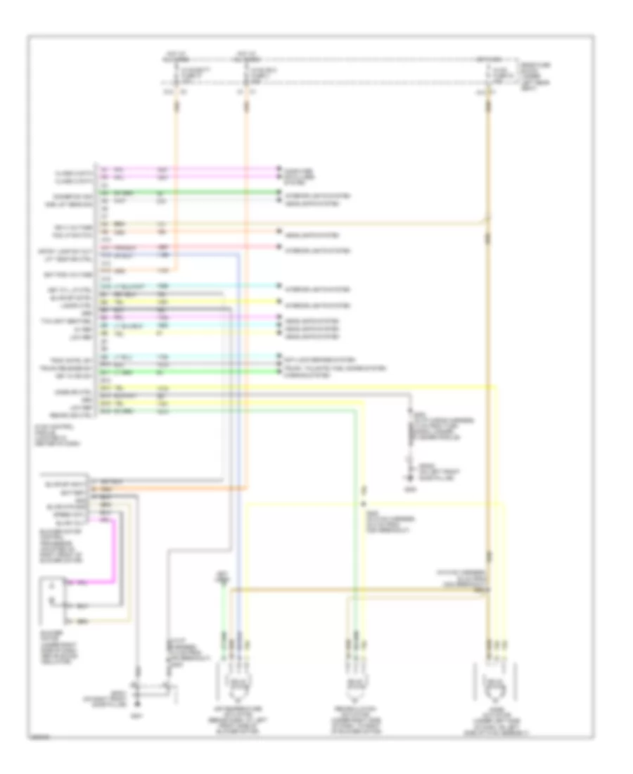
Manual A/C Wiring Diagram (1 of 2) for Pontiac Bonneville GXP 2005
List of elements for Manual A/C Wiring Diagram (1 of 2) for Pontiac Bonneville GXP 2005:
- (in hvac harness, 30 cm from c204 breakout) s221
- (in i/p harness, 6.5 cm from ipm breakout) s203
- (not used)
- 5v ref
- A10
- A11
- A12
- A13
- A14
- A15
- A16
- Air temperature actuator (behind dash, at left front side of blower motor)
- Amb lgt sens sig
- Anti-lock brakes system
- B10
- B11
- B12
- B13
- B14
- B15
- B16
- Bat pos voltage
- Battery
- Blower motor (under right side of dash, above sound insulator)
- Blower motor control processor (mounted on right front of blower motor)
- Blwr mtr gnd
- Blwr sp cntrl
- Blwr sp input
- Blwr volt
- C1 a10
- Class 2 data
- Computer data lines system
- Crtsy lamp sw out
- D12
- Dimmer sw sig
- Fog lp switch
- G200
- G201
- Gnd
- Grd
- Headlights system
- Hot at all times
- Hot in on
- Hvac batt fuse 37 10a
- Hvac blo fuse 2 30a
- Hvac control module (located in center of dash)
- Hvac fuse 33 10a
- Ign 3 voltage
- Interior lights system
- Key cyl lp ctrl
- Key in ign sw
- Lamps ctrl
- Lft temp dr ctrl
- Low ref
- Mode actuator (under left side of dash, on left side of hvac assembly)
- Mode dr ctrl
- Rear fuse block (under left rear seat)
- Recirc dr ctrl
- Recirculation actuator (under right side of dash, to right of blower motor)
- S222 (in hvac harness, 23.5 cm from c204 breakout)
- S253 (in i/p wiring harness, 13 cm from turn signal hazard flasher module)
- Solid state
- Sp200 (on left front door pillar)
- Sp201 (on right front door pillar)
- Speed cntl
- Trac cntrl sw
- Trunk release sw
- Trunk, tailgate, fuel doors system
- Twilight sentinel
- Warning system
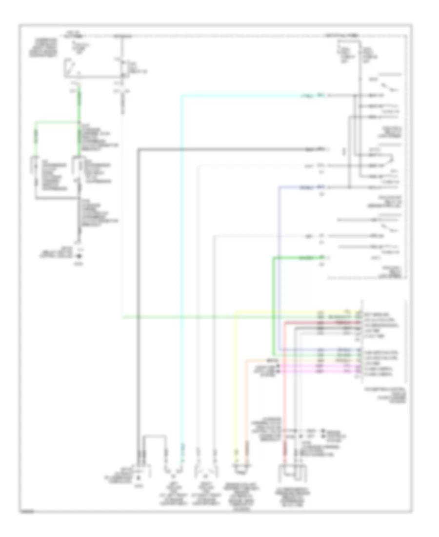
Manual A/C Wiring Diagram (2 of 2) for Pontiac Bonneville GXP 2005
List of elements for Manual A/C Wiring Diagram (2 of 2) for Pontiac Bonneville GXP 2005:
- (in engine harness, 6.5 cm
- 5 volt ref
- A/c clu fuse 15a
- A/c clu relay 32
- A/c clutch ctrl
- A/c compressor clutch (on front of a/c compressor)
- A/c compressor clutch diode (on wiring harness, near a/c compressor)
- A/c refrigerant pressure sensor (behind a/c compressor, on a/c line)
- A/c sensor signal
- A10
- A11
- B10
- B11
- C10
- C11
- Class 2 serial
- Computer data lines system
- Cool fan 1 fuse 47 30a
- Cool fan 2 fuse 46 30a
- Coolfan 1 relay (low speed)
- Coolfan 2 relay 37 (high speed)
- Coolfan s/p relay 39 (series/parallel)
- D10
- E10
- E11
- Ect sens sig
- Engine controls system
- Engine coolant temperature (ect) sensor (on rear of
- Engine, near thermostat housing)
- F11
- From idle air control valve connector breakout)
- G10
- G103
- G105
- G11
- High spd fan ctrl
- Hot at all times
- Hot in on
- Left cooling fan (at left front of engine compartment)
- Low ref
- Low spd fan ctrl
- Powertrain control module (in air cleaner housing)
- Right cooling fan (at right front of engine compartment)
- S106
- S108 (in engine harnes, 18 cm from a/c compressor clutch connector breakout)
- S109
- Sp103 (in front of underhood fuse block)
- Sp105 (below ignition control module)
- T10
- T11
- Underhood fuse block (right front side of engine compartment)
- V10
- V11
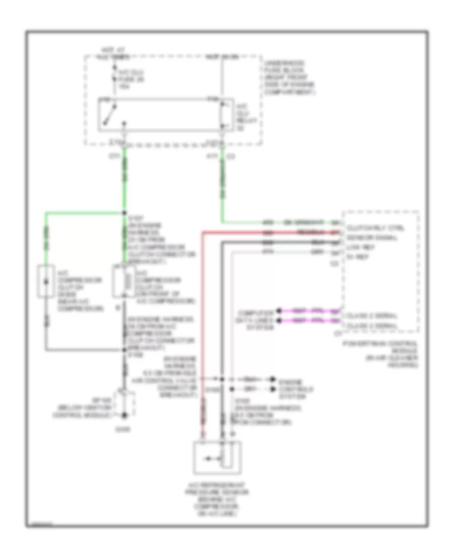
3.8L VIN K
3.8L VIN K, Compressor Wiring Diagram for Pontiac Bonneville GXP 2005
List of elements for 3.8L VIN K, Compressor Wiring Diagram for Pontiac Bonneville GXP 2005:
- (in engine harness, 18 cm from a/c compressor clutch connector breakout) s108
- (in engine harness, 6.5 cm from idle air control valve connector breakout)
- 5v ref
- A/c clu fuse 26 15a
- A/c clu relay
- A/c compressor clutch (on front of a/c compressor)
- A/c compressor clutch diode (near a/c compressor)
- A/c refrigerant pressure sensor (behind a/c compressor, on a/c line)
- Class 2 serial
- Clutch rly ctrl
- Computer data lines system
- Engine controls system
- G105
- Hot at all times
- Hot in on
- Low ref
- Powertrain control module (in air cleaner housing)
- S106
- Sensor signal
- Sp105 (below ignition control module)
- T10
- T11
- Underhood fuse block (right front side of engine compartment)
- V10
- V11
4.6L VIN A
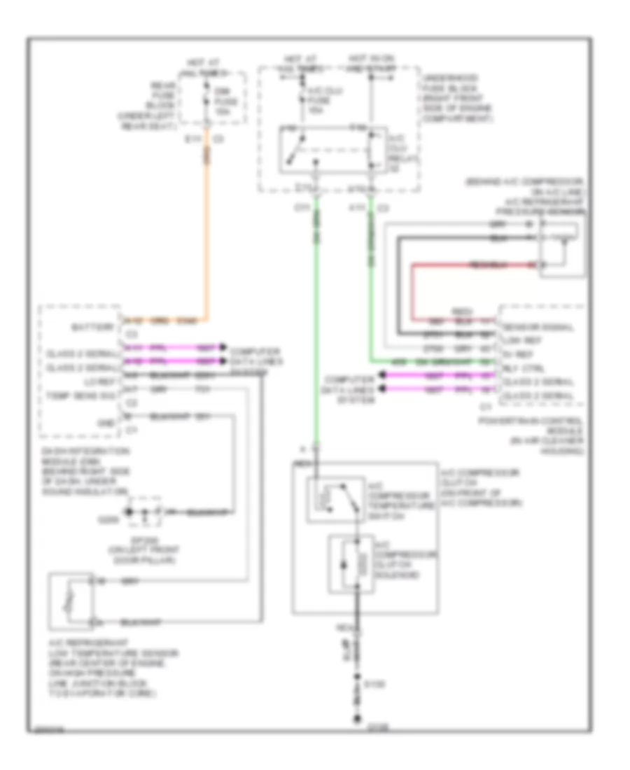
4.6L VIN A, Compressor Wiring Diagram for Pontiac Bonneville GXP 2005
List of elements for 4.6L VIN A, Compressor Wiring Diagram for Pontiac Bonneville GXP 2005:
- (behind a/c compressor, on a/c line) a/c refrigerant pressure sensor
- 5v ref
- A/c clu fuse 15a
- A/c clu relay
- A/c compressor clutch (on front of a/c compressor)
- A/c compressor clutch solenoid
- A/c compressor temperature switch
- A/c refrigerant low temperature sensor (rear center of engine, on high pressure line junction block to evaporator core)
- A11 class 2 serial
- A12
- A12 class 2 serial
- Battery
- C3 e11
- Class 2 serial
- Computer data lines system
- Dash integration module (dim) (behind right side of dash, under sound insulator)
- Dim fuse 10a
- G108
- G200
- Gnd
- Hot at all times
- Hot in on and start
- Lo ref
- Low ref
- Nca
- Powertrain control module (in air cleaner housing)
- Rear fuse block (under left rear seat)
- Rly ctrl
- S130
- Sensor signal
- Sp200 (on left front door pillar)
- T10
- T11
- Temp sens sig
- Underhood fuse block (right front side of engine compartment)
- V10
- V11