AIR CONDITIONING
Automatic A/C Wiring Diagram (1 of 2) for Pontiac Bonneville SSEi 2000

List of elements for Automatic A/C Wiring Diagram (1 of 2) for Pontiac Bonneville SSEi 2000:
- (hvac harn, near hvac blower)
- (hvac harn, near hvac blower) s221
- (i/p harn, 6 cm from 30 pin in- line conn, near i/p)
- 5v ref feed
- A10
- A11
- A12
- Air inlet act cntl
- Air inlet act sig
- Air inlet actuator (under right side of dash, right of blower motor)
- Air mix act cntl
- Air mix act sig
- Amb air temp sig
- Amb light sens
- Ambient air temp sensor (on hood latch support)
- Battery
- Blwr sp cntrl
- C1 a1
- C11
- C12
- C13
- Computer data lines system
- D11
- D12
- D16
- Data line
- Driver air mix actuator (on left side of hvac module)
- G200 (lower left "a" pillar)
- G203 (lower right "a" pillar)
- Ground
- Heater & a/c control
- Hot at all times
- Hot in on
- Hvac (batt) fuse 15a
- Hvac blo fuse 30a
- Hvac fuse 10a
- Ign
- Ign 3 rr fuse 10a
- Illum
- Illum grd
- In air temp sig
- Inside air temp sensor (near left center dash panel)
- Instrument panel module (ipm) (behind left side of dash)
- Interior lights system
- Kdd clock
- Kdd data
- Left heater temp sensor (under left side of dash, in sound insulator)
- Left panel temp sensor (in left dash duct, behind outer vent)
- Lh htr temp sig
- Lh panel temp sig
- Lh sun load sens
- Logic grd
- Mode act cntl
- Mode door actuator (under left side of dash, on left side of hvac module)
- Mode dr pos sens
- Motor ground
- Nca
- Passenger air mix actuator (under right side of dash, on right side of hvac module)
- Rear fuse block
- Rh htr temp sig
- Rh panel temp sig
- Rh sun load sens
- Right heater temp sensor (under right side of dash, in sound insulator)
- Right panel temp sensor (in right dash duct, behind outer vent)
- S203
- S204
- S205
- S222
- Sensor grd
- Solid state
- Sunload sensor & ambient light sensor (on top center of dash, in defroster grille)
- Tan
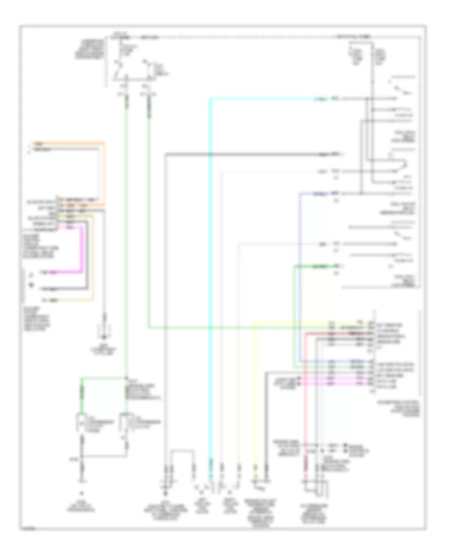
Automatic A/C Wiring Diagram (2 of 2) for Pontiac Bonneville SSEi 2000
List of elements for Automatic A/C Wiring Diagram (2 of 2) for Pontiac Bonneville SSEi 2000:
- (engine harn, 6.5 cm from iac valve breakout)
- 5 v
- A/c clu fuse 15a
- A/c clu relay
- A/c compressor clutch
- A/c compressor clutch diode
- A/c enable
- A/c pressure sensor (behind a/c compressor, on a/c line)
- B10
- Battery
- Blower control module (under right side of dash, above blower motor)
- Blower motor (under right side of dash, above sound insulator)
- Blwr mtr grd
- Blwr sp input
- Blwr volt
- Computer data lines system
- Cool fan 1 fuse 30a
- Cool fan 1 relay (low speed)
- Cool fan 2 fuse 30a
- Cool fan 2 relay (high speed)
- Cool fan s/p relay (series/parallel)
- D10
- Data line
- E10
- Ect sens grd
- Ect sens sig
- Engine controls system
- Engine coolant temperature sensor (on rear of
- Engine, near thermostat housing)
- F11
- G101 (mounted to inner body panel, forward of underhood fuse block)
- G129 (on top of transmission)
- G203 (lower right "a" pillar)
- Grd
- High spd fan cntrl
- Hot at all times
- Hot in on
- Left cooling fan motor
- Low spd fan cntrl
- Powertrain control module (pcm) (in air cleaner housing)
- Right cooling fan motor
- S106
- S108
- Sensor grd
- Sensor signal
- Speed cntl
- Underhood fuse block (right front side of engine compartment)
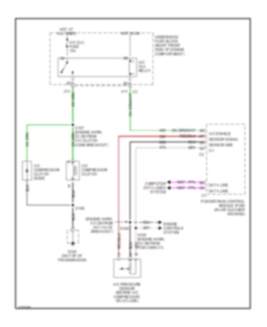
Compressor Wiring Diagram for Pontiac Bonneville SSEi 2000
List of elements for Compressor Wiring Diagram for Pontiac Bonneville SSEi 2000:
- (engine harn, 6.5 cm from iac valve breakout)
- 5 v
- A/c clu fuse 15a
- A/c clu relay
- A/c compressor clutch
- A/c compressor clutch diode
- A/c enable
- A/c pressure sensor (behind a/c compressor, on a/c line)
- Computer data lines system
- Data line
- Engine controls system
- G129 (on top of transmission)
- Hot at all times
- Hot in on
- Powertrain control module (pcm) (in air cleaner housing)
- S106
- S108
- Sensor grd
- Sensor signal
- Underhood fuse block (right front side of engine compartment)
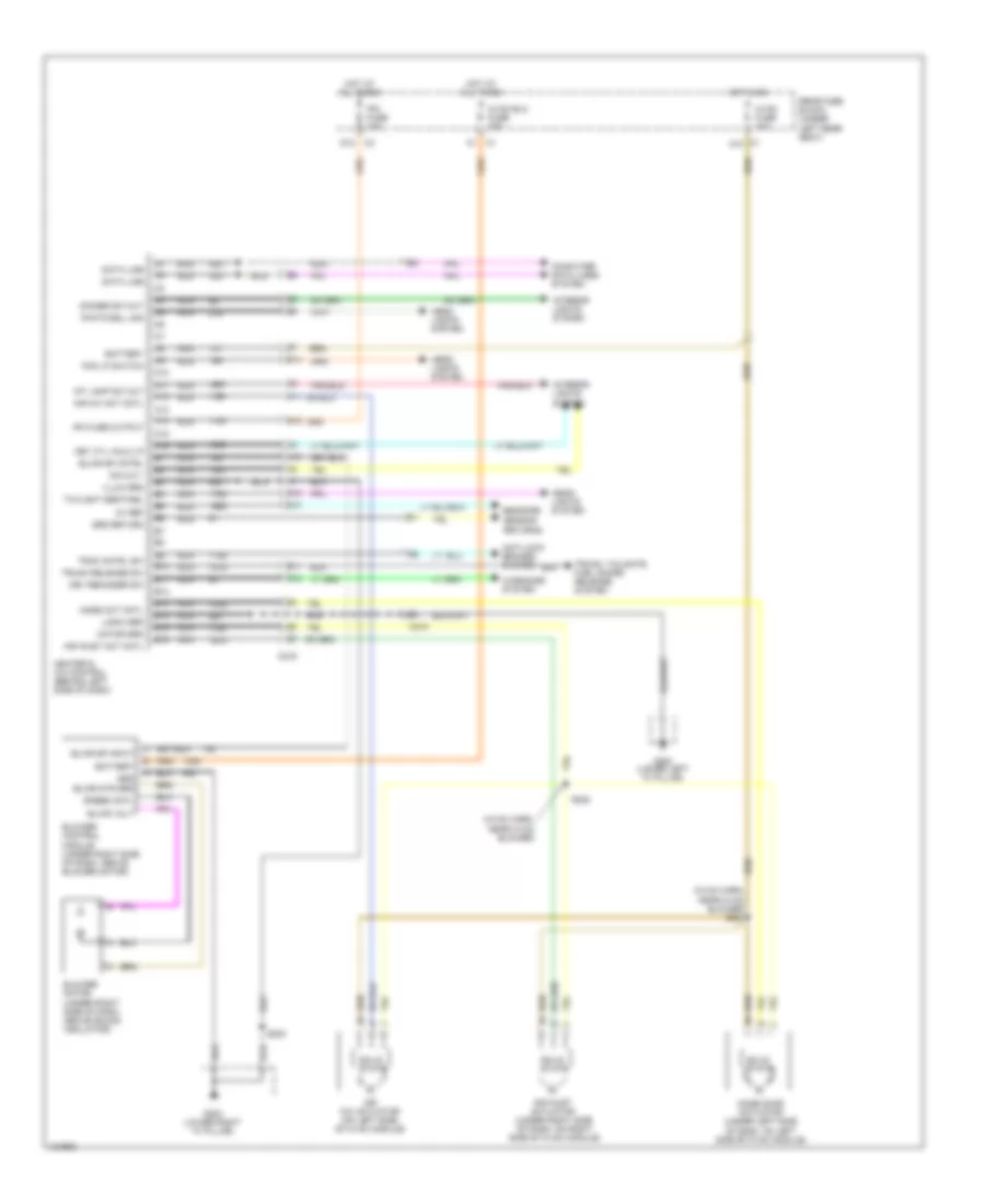
Manual A/C Wiring Diagram (1 of 2) for Pontiac Bonneville SSEi 2000
List of elements for Manual A/C Wiring Diagram (1 of 2) for Pontiac Bonneville SSEi 2000:
- (hvac harn, near hvac blower)
- (hvac harn, near hvac blower) s221
- 5v ref
- A10
- A11
- A12
- A13
- A14
- A15
- A16
- Air inlet act cntl
- Air inlet actuator (under right side of dash, on right side of hvac module)
- Air mix act cntl
- Air mix actuator (on left side of hvac module)
- Anti-lock brakes system
- B10
- B11
- B12
- B13
- B14
- B15
- B16
- Battery
- Blower control module (under right side of dash, above blower motor)
- Blower motor (under right side of dash, above sound insulator)
- Blwr mtr grd
- Blwr sp cntrl
- Blwr sp input
- Blwr volt
- C1 a10
- C215
- C216
- Computer data lines system
- D12
- Data line
- Dim out
- Dimmer sw out
- Fog lp switch
- G200 (lower left "a" pillar)
- G203 (lower right "a" pillar)
- Grd
- Grd return
- Head- lights system
- Heater & a/c control (behind left side of dash)
- Hot at all times
- Hot in on
- Hvac blo fuse 30a
- Hvac fuse 10a
- Illum grd
- Int lamp sw out
- Interior lights system
- Ipm fuse 10a
- Ipm fuse output
- Key cyl halo lp
- Key reminder sw
- Logic grd
- Mode act cntl
- Mode door actuator (under left side of dash, on left side of hvac module)
- Motor grd
- Nca
- Photocell sig
- Rear fuse block (under left rear seat)
- S203
- S222
- Sensor returns
- Sensors
- Solid state
- Speed cntl
- Trac cntrl sw
- Trunk release sw
- Trunk, tailgate, fuel doors release system
- Twilight sentinel
- Warnings system
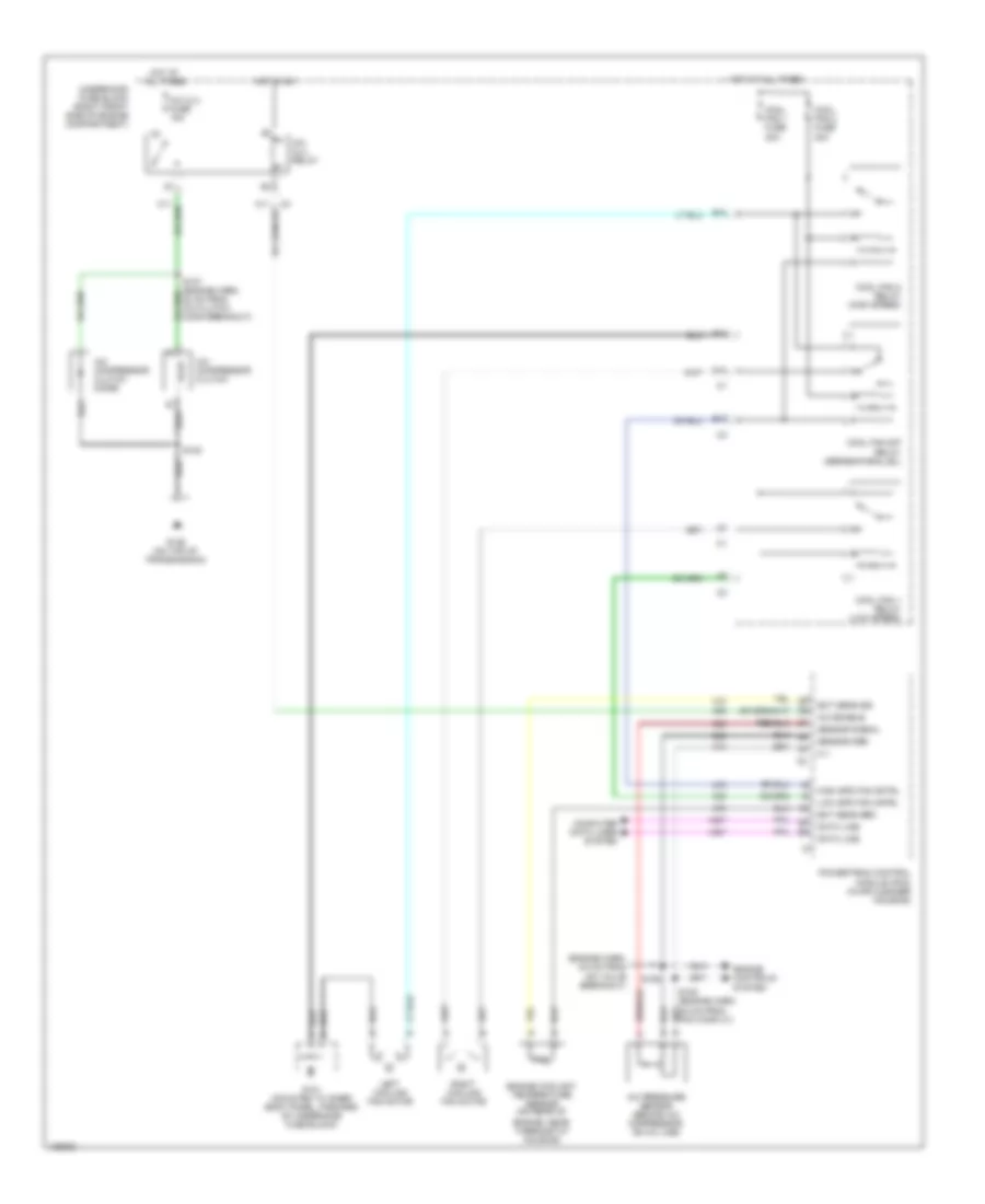
Manual A/C Wiring Diagram (2 of 2) for Pontiac Bonneville SSEi 2000
List of elements for Manual A/C Wiring Diagram (2 of 2) for Pontiac Bonneville SSEi 2000:
- (engine harn, 6.5 cm from iac valve breakout)
- 5 v
- A/c clu fuse 15a
- A/c clu relay
- A/c compressor clutch
- A/c compressor clutch diode
- A/c enable
- A/c pressure sensor (behind a/c compressor, on a/c line)
- B10
- Computer data lines system
- Cool fan 1 fuse 30a
- Cool fan 1 relay (low speed)
- Cool fan 2 fuse 30a
- Cool fan 2 relay (high speed)
- Cool fan s/p relay (series/parallel)
- D10
- Data line
- E10
- Ect sens grd
- Ect sens sig
- Engine controls system
- Engine coolant temperature sensor (on rear of
- Engine, near thermostat housing)
- F11
- G101 (mounted to inner body panel, forward of underhood fuse block)
- G129 (on top of transmission)
- High spd fan cntrl
- Hot at all times
- Hot in on
- Left cooling fan motor
- Low spd fan cntrl
- Powertrain control module (pcm) (in air cleaner housing)
- Right cooling fan motor
- S106
- S108
- Sensor grd
- Sensor signal
- Underhood fuse block (right front side of engine compartment)