AIR CONDITIONING
3.8L
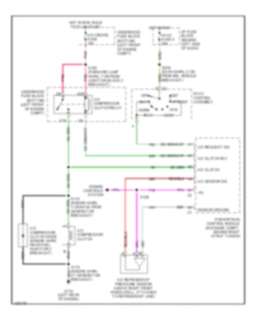
3.8L VIN K, Compressor Wiring Diagram for Pontiac Firebird 2001

List of elements for 3.8L VIN K, Compressor Wiring Diagram for Pontiac Firebird 2001:
- (bottom) (left front of engine compt)
- (engine harn, 8 cm from pcm breakout)
- (forward lamp harn, 14 cm from pcm breakout)
- +5v
- A/c clutch rly
- A/c compressor clutch
- A/c compressor clutch diode (engine harn, near fuel injector 2 breakout)
- A/c compressor clutch relay
- A/c refrigerant pressure sensor (above right front wheelwell, attached to refrigerant line)
- A/c request sig
- A/c sensor sig
- A/c-cruise fuse 15a
- At generator breakout)
- Bi-lv
- C10
- D10
- Def
- Engine controls system
- G114 (left rear of engine)
- Hot in run
- Hot in run, bulb test or start
- Htr
- Htr/def
- Hvac control assembly
- Hvac fuse 6 20a
- I/p fuse block (behind left side of dash)
- Max
- Nca
- Norm
- Off
- Pnk
- Powertrain control module (in engine compt, behind right strut tower)
- S111
- S114 (engine harn, 3 cm back from generator breakout)
- S121
- S165 (forward lamp harn, 7 cm from junction block 2 breakout)
- S248 (dash harn, 2 cm from drl module breakout)
- Sensor ground
- Underhood fuse block
- Vent
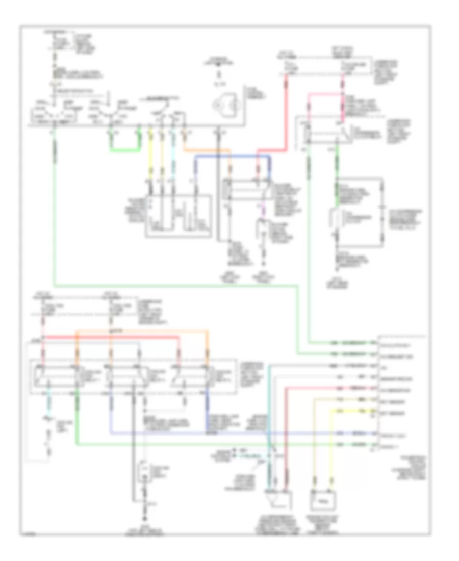
3.8L VIN K, Manual A/C Wiring Diagram for Pontiac Firebird 2001
List of elements for 3.8L VIN K, Manual A/C Wiring Diagram for Pontiac Firebird 2001:
- (bottom) (left front of engine compt)
- (engine harn, 8 cm from pcm breakout)
- (forward lamp harn, 14 cm from pcm breakout)
- (forward lamp harn, near right radiator support) s166
- +5v
- 0.31 ohm total
- 0.61 ohm
- 1.85 ohm
- A/c clutch rly
- A/c compressor clutch
- A/c compressor clutch diode (engine harn, near breakout to fuel inj 2)
- A/c compressor clutch relay
- A/c refrigerant pressure sensor (above right front wheelwell, attached to refrigerant line)
- A/c request sig
- A/c sensor sig
- A/c-cruise fuse 15a
- B10
- Bi-lv
- Blower motor (behind right side of dash)
- Blower motor relay (center of dash, on inflatable restraint dash module bracket)
- Blower motor resistor assembly (in hvac module)
- Blower switch
- C tan
- C10
- Cool fan fuse 10a
- Cool fan fuse 40a
- Cooling fan (left)
- Cooling fan (right)
- Cooling fan relay 1
- Cooling fan relay 2
- Cooling fan relay 3
- D10
- Def
- Ect sensor
- Engine controls system
- Engine coolant temperature sensor (below throttle body)
- Fan rly 1
- Fan rly 2 & 3
- G108 (top left side of radiator support)
- G114 (left rear of engine)
- G200 (left kick panel)
- G203 (right kick panel)
- Hot at all times
- Hot in run
- Hot in run, bulb test or start
- Htr
- Htr/def
- Hvac control assembly
- Hvac fuse 6 20a
- I/p 1 fuse 40a
- I/p fuse block (behind left side of dash)
- Interior lights system
- Max
- Nca
- Norm
- Off
- Pnk
- Powertrain control module (in engine compt, behind right strut tower)
- Red
- S111
- S113
- S115 (engine harn, at generator breakout)
- S121
- S165 (forward lamp harn, 7 cm from junction block 2 breakout)
- S169
- S179
- S216 (dash harn, 10 cm from cluster breakout)
- S248 (dash harn, 2 cm from drl module breakout)
- Selector switch
- Sensor ground
- Tan
- Underhood fuse block
- Underhood fuse block (top) (left front corner of engine compt)
- Vent
5.7L
5.7L VIN G, Compressor Wiring Diagram for Pontiac Firebird 2001
List of elements for 5.7L VIN G, Compressor Wiring Diagram for Pontiac Firebird 2001:
- (bottom) (left front of engine compt)
- +5v
- A/c clutch
- A/c clutch rly
- A/c compressor clutch
- A/c compressor clutch diode (engine harn, near fuel injector 2 breakout)
- A/c compressor clutch relay
- A/c refrigerant pressure sensor (above right front wheelwell, attached to refrigerant line)
- A/c request sig
- A/c sensor sig
- A/c-cruise fuse 15a
- At generator breakout)
- Bi-lv
- C10
- D10
- Def
- Engine controls system
- G114 (left rear of engine)
- Hot in run
- Hot in run, bulb test or start
- Htr
- Htr/def
- Hvac control assembly
- Hvac fuse 6 20a
- I/p fuse block (behind left side of dash)
- Max
- Nca
- Norm
- Off
- Pnk
- Powertrain control module (in engine compt, behind right strut tower)
- S114 (engine harn, 3 cm back from generator breakout)
- S128
- S165 (forward lamp harn, 7 cm from junction block 2 breakout)
- S248 (dash harn, 2 cm from drl module breakout)
- Sensor ground
- Underhood fuse block
- Vent
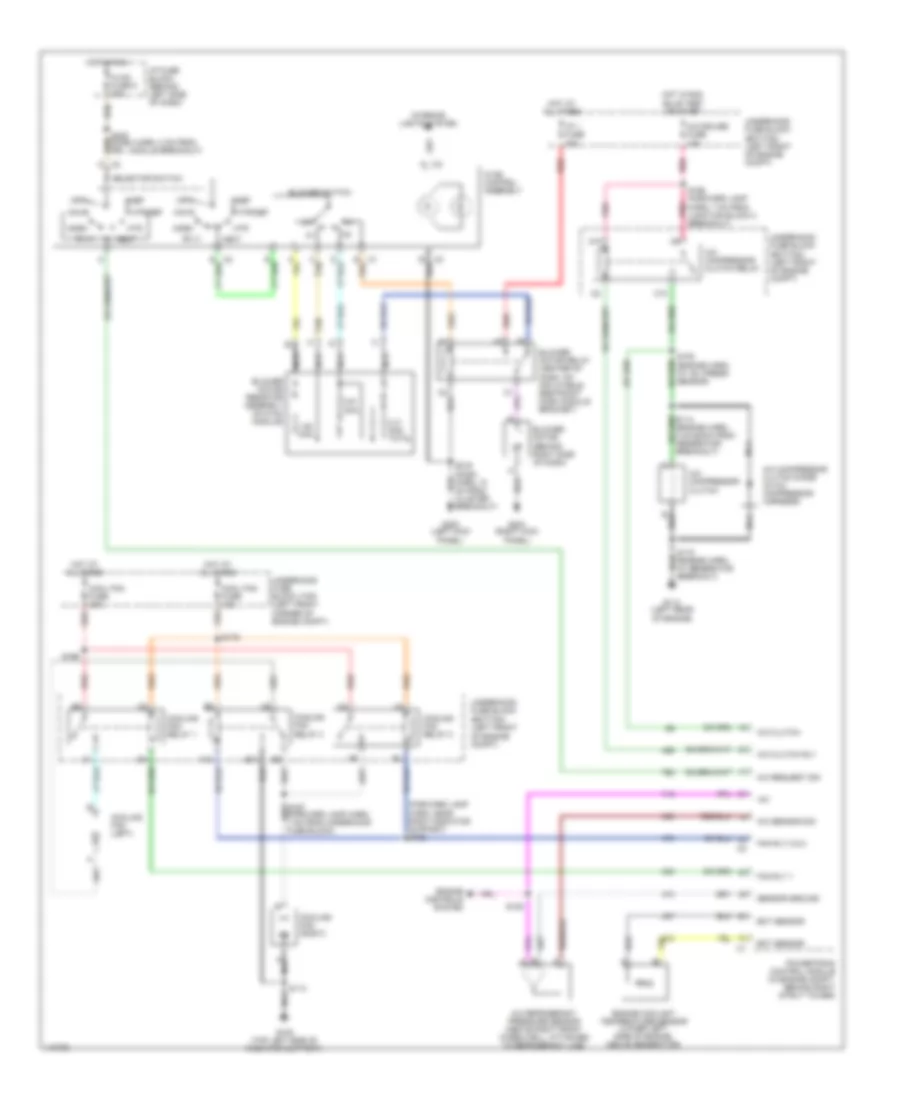
5.7L VIN G, Manual A/C Wiring Diagram for Pontiac Firebird 2001
List of elements for 5.7L VIN G, Manual A/C Wiring Diagram for Pontiac Firebird 2001:
- (bottom) (left front of engine compt)
- (forward lamp harn, near right radiator support) s166
- +5v
- 0.31 ohm total
- 0.61 ohm
- 1.85 ohm
- A/c clutch
- A/c clutch rly
- A/c compressor clutch
- A/c compressor clutch diode (in a/c compressor harness)
- A/c compressor clutch relay
- A/c refrigerant pressure sensor (above right front wheelwell, attached to refrigerant line)
- A/c request sig
- A/c sensor sig
- A/c-cruise fuse 15a
- B10
- Bi-lv
- Blower motor (behind right side of dash)
- Blower motor relay (center of dash, on inflatable restraint dash module bracket)
- Blower motor resistor assembly (in hvac module)
- Blower switch
- C tan
- C10
- Cool fan fuse 10a
- Cool fan fuse 40a
- Cooling fan (left)
- Cooling fan (right)
- Cooling fan relay 1
- Cooling fan relay 2
- Cooling fan relay 3
- D10
- Def
- Ect sensor
- Engine controls system
- Engine coolant temperature sensor (lower left side of engine, above generator)
- Fan rly 1
- Fan rly 2 & 3
- G108 (top left side of radiator support)
- G114 (left rear of engine)
- G200 (left kick panel)
- G203 (right kick panel)
- Hot at all times
- Hot in run
- Hot in run, bulb test or start
- Htr
- Htr/def
- Hvac control assembly
- Hvac fuse 6 20a
- I/p 1 fuse 40a
- I/p fuse block (behind left side of dash)
- Interior lights system
- Max
- Nca
- Norm
- Off
- Pnk
- Powertrain control module (in engine compt, behind right strut tower)
- Red
- S105 (engine harn, at ac/ press sensor)
- S113
- S115 (engine harn, at generator breakout)
- S128
- S165 (forward lamp harn, 7 cm from junction block 2 breakout)
- S169
- S179
- S216 (dash harn, 10 cm from cluster breakout)
- S248 (dash harn, 2 cm from drl module breakout)
- Selector switch
- Sensor ground
- Tan
- Underhood fuse block
- Underhood fuse block (top) (left front corner of engine compt)
- Vent