AIR CONDITIONING
A/C Wiring Diagram for Pontiac Firebird Formula 1998

List of elements for A/C Wiring Diagram for Pontiac Firebird Formula 1998:
- (3.8l: eng harn, 3 cm back from generator breakout) (5.7l: eng harn, 17 cm back from a/c compressor clutch conn)
- (3.8l: eng harn, 7.5 cm from inj 4 breakout) (5.7l: eng harn, 33 cm back from a/c comp clutch breakout)
- (3.8l: eng harn, at generator breakout) (5.7l: eng harn, 20 cm back from a/c clutch breakout)
- (5.7l on lower left side of engine)
- (eng harn, at a/c refrigerant pressure sensor breakout)
- (forward lamp harn)
- (forward lamp harn, near right radiator support)
- (in underhood electrical center 1)
- (near top left side of the radiator support)
- +5v
- 0.31 ohm total
- 0.61 ohm
- 1.85 ohm
- 3.8l
- 407 (or 720)
- 5.7l
- A/c clutch diode (1 amp)
- A/c compressor clutch
- A/c compressor relay (in underhood electrical center 2)
- A/c refrigerant pressure sensor (above right front wheelhouse, on refrigerant line)
- A/c request
- A/c-cruise fuse (mini) 15a
- Bi-lv
- Blend
- Blower motor
- Blower motor relay (on inflatable restraint dash module bracket)
- Blower resistor (in hvac module)
- Blower switch
- C 1995 vftc
- C tan
- Center 2
- Clutch status
- Compressor ctrl
- Cool fan fuse (maxi) 40a
- Cooling fan fuse (mini) 10a
- D10
- Def
- Ect sensor input
- Engine coolant temperature sensor (3.8l: below throttle body)
- Engine cooling fan relay 1
- Engine cooling fan relay 2 (in underhood electrical center 1)
- Engine cooling fan relay 3 (in underhood electrical center 1)
- Fan rly 1 control
- Fan rly 2 & 3 control
- G108
- G112 (left side of engine)
- G200 (left kick panel)
- G203 (right kick panel)
- Hot at all times
- Hot in run
- Hot in run, bulb test or start
- Htr
- Htr/ def
- Htr/def
- Hvac control (blower switch contacts are make before break contacts)
- Hvac fuse 6 20a
- I/p 1 fuse (maxi) 40a
- I/p fuse block
- Interior lights system
- Left engine cooling fan
- Max
- Nca
- Norm
- Off
- Pnk
- Powertrain control module (in engine compt, rear of right strut tower)
- Red
- Right engine cooling fan
- S105
- S114
- S115
- S165 (forward lamp harn, 7cm from pnk underhood electrical center 2 breakout)
- S166
- S169 (forward lamp harn, 6 cm into underhood electrical center 1 breakout)
- S179
- S216 (i/p harn, 10 cm from i/p cluster breakout)
- S248 (i/p harn, 2 cm from radio connectors breakout)
- Selector switch
- Sensor ground
- Sensor sig
- Tan
- Underhood electrical
- Underhood electrical center 1
- Vent
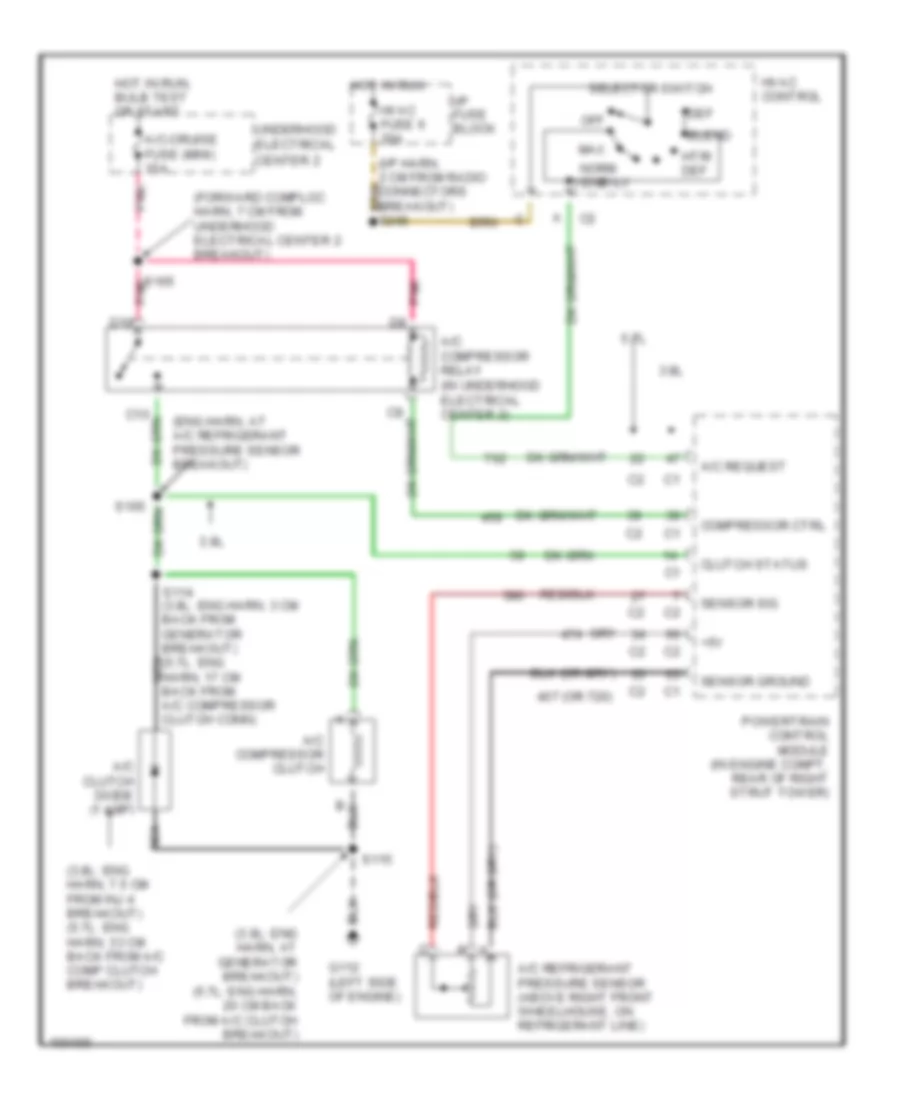
Compressor Wiring Diagram for Pontiac Firebird Formula 1998
List of elements for Compressor Wiring Diagram for Pontiac Firebird Formula 1998:
- (3.8l: eng harn, 7.5 cm from inj 4 breakout) (5.7l: eng harn, 33 cm back from a/c comp clutch breakout)
- (3.8l: eng harn, at generator breakout) (5.7l: eng harn, 20 cm back from a/c clutch breakout)
- (eng harn, at a/c refrigerant pressure sensor breakout)
- (forward comploc harn, 7 cm from underhood electrical center 2 breakout)
- +5v
- 3.8l
- 407 (or 720)
- 5.7l
- A/c clutch diode (1 amp)
- A/c compressor clutch
- A/c compressor relay (in underhood electrical center 2)
- A/c refrigerant pressure sensor (above right front wheelhouse, on refrigerant line)
- A/c request
- A/c-cruise fuse (mini) 15a
- Bi-lv
- Blend
- Center 2
- Clutch status
- Compressor ctrl
- D10
- Def
- G112 (left side of engine)
- Hot in run
- Hot in run, bulb test or start
- Htr/ def
- Hvac control
- Hvac fuse 6 20a
- I/p fuse block
- Max
- Nca
- Norm
- Off
- Pnk
- Powertrain control module (in engine compt, rear of right strut tower)
- S105
- S114 (3.8l: eng harn, 3 cm back from generator breakout) (5.7l: eng harn, 17 cm back from a/c compressor clutch conn)
- S115
- S165 pnk
- Selector switch
- Sensor ground
- Sensor sig
- Underhood electrical
- Vent