AIR CONDITIONING
2.2L VIN F
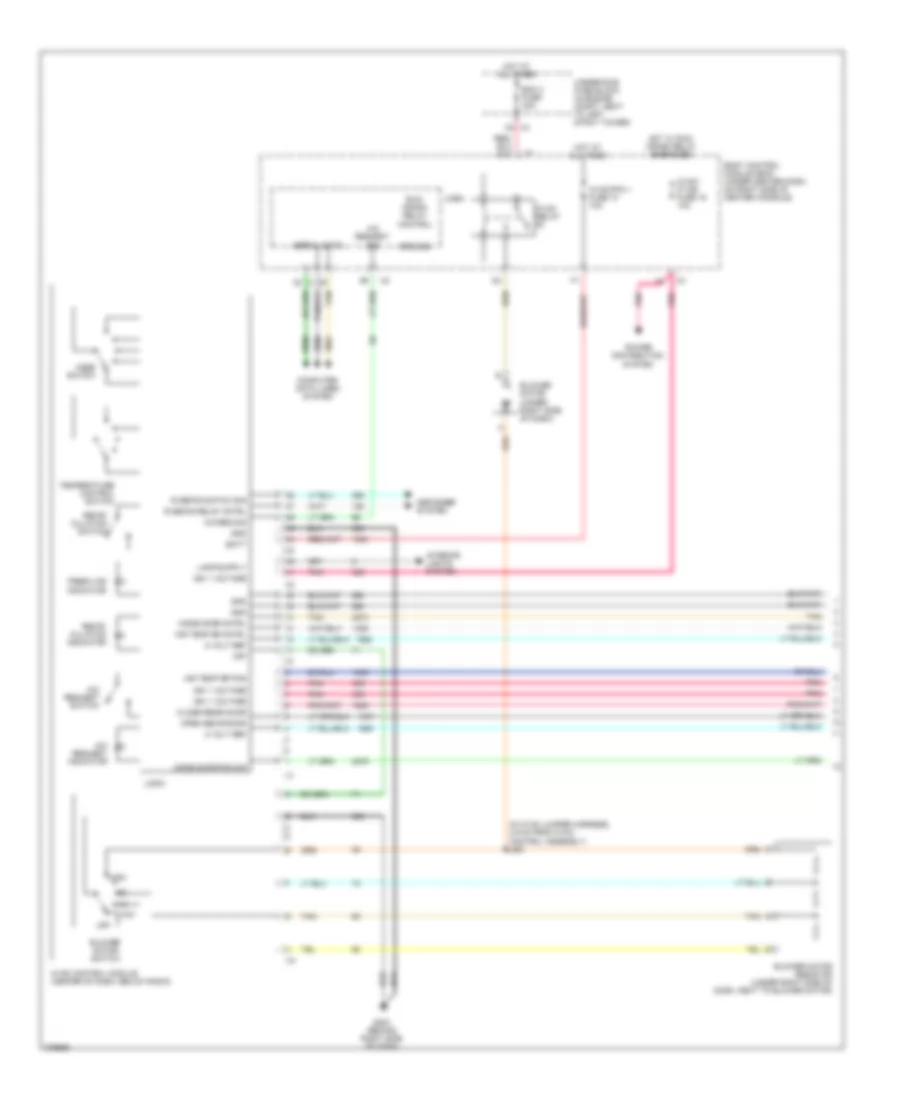
2.2L VIN F, Compressor Wiring Diagram for Pontiac G5 GT 2008

List of elements for 2.2L VIN F, Compressor Wiring Diagram for Pontiac G5 GT 2008:
- 5v ref
- A/c clutch fuse 10a
- A/c clutch relay
- A/c compressor clutch (left front of engine)
- A/c compressor clutch diode
- A/c refrigerant pressure sensor (in right front of engine compt, on a/c line, near compressor)
- A/c req sig
- A/c request indicator
- A/c request sig
- A/c request switch
- Batt
- Body control module (bcm) (under center dash, on right side of center console)
- Computer data lines system
- Ect sig
- Engine control module (ecm) (left side of engine compt, in front of underhood fuse block)
- Engine coolant temperature (ect) sensor (rear of engine, near exhaust manifold)
- G101 (left side of engine compt, under coolant reservoir)
- G203 (behind right side of dash)
- Gnd
- Hot at all times
- Hot in run or start
- Hot w/ run/ crank relay energized
- Hvac control module (center of dash, below radio)
- Hvac/ ip ign fuse 16 10a
- Hvac/pk3 + fuse 10 10a
- Ign 1 voltage
- Logic
- Low ref
- Pnk
- Power distribution system
- Press sens sig
- Rly ctrl
- Serial data
- Tan
- Underhood fuse block (in engine compt, next to left strut tower)
- X3 f2
- X5 a4
2.2L VIN F, Manual A/C Wiring Diagram (1 of 2) for Pontiac G5 GT 2008
List of elements for 2.2L VIN F, Manual A/C Wiring Diagram (1 of 2) for Pontiac G5 GT 2008:
- (in hvac jumper harness, 4.9 cm from hvac control assembly) j261
- 5 volt ref
- A/c req sig
- A/c request indicator
- A/c request sig
- A/c request switch
- Air temp dr cntrl
- Air temp dr pos
- Batt
- Bcm 3 fuse 30a
- Blower motor (under right side of dash)
- Blower motor resistor (under right side of dash, next to blower motor)
- Blower motor switch
- Body control module (bcm) (under center dash, on right side of center console)
- Close recir door
- Computer data lines system
- Defogger system
- Fresh air indicator
- G203 (behind right side of dash)
- Gnd
- Ground
- High
- Hot at all times
- Hot w/ run/ crank relay energized
- Hvac control module (center of dash, below radio)
- Hvac relay
- Hvac/ ip ign fuse 16 10a
- Hvac/pk3 + fuse 10 10a
- Ign 1 voltage
- Interior lights system
- Logic
- Low
- Mode door cntrl
- Mode door pos sig
- Mode switch
- Off
- Open recir door
- Pnk
- Power distribution system
- R defog relay cntrl
- R defog switch sig
- Recir- culation indicator
- Recir- culation switch
- Run/ crank relay control
- Serial data
- Tan
- Temperature control switch
- Underhood fuse block (in engine compt, next to left strut tower)
- X4 c2
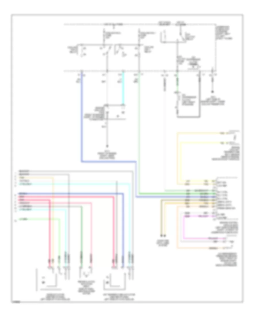
2.2L VIN F, Manual A/C Wiring Diagram (2 of 2) for Pontiac G5 GT 2008
List of elements for 2.2L VIN F, Manual A/C Wiring Diagram (2 of 2) for Pontiac G5 GT 2008:
- 5v ref
- A/c cltch fuse 10a
- A/c clutch relay
- A/c compressor clutch (left front of engine)
- A/c compressor clutch diode
- A/c refrigerant pressure sensor (right front of engine compt, on a/c line, near compressor)
- A1 x5
- A11
- Air temperature actuator (center of dash, left side of hvac module)
- Computer data lines system
- Cooling fan 1 fuse 30a
- Cooling fan 1 relay
- Cooling fan 2 fuse 30a
- Cooling fan 2 relay
- E10
- Ect sig
- Engine control module (ecm) (left side of engine compt, in front of underhood fuse block)
- Engine coolant temperature (ect) sensor (rear of engine, near exhaust manifold)
- Engine cooling fan (front of engine compt, attached to radiator)
- F10
- G101 (left side of engine compt, under coolant reservoir)
- G111 (front of engine compt, near cooling fans)
- Hot at all times
- Hot in run or start
- Low ref
- Mode actuator (center of dash, left side of hvac module)
- Pnk
- Press sens sig
- Recirculation actuator (right side of dash, above blower motor)
- Rly ctrl
- Serial data
- Tan
- Underhood fuse block (in engine compt, next to left strut tower)
- X3 f2
- X5 a4
2.4L VIN B
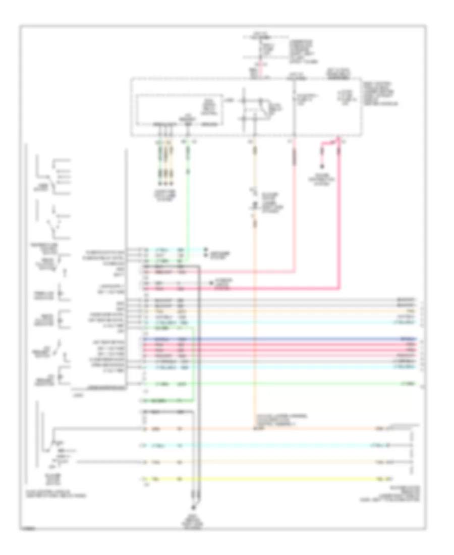
2.4L VIN B, Compressor Wiring Diagram for Pontiac G5 GT 2008
List of elements for 2.4L VIN B, Compressor Wiring Diagram for Pontiac G5 GT 2008:
- 5v ref
- A/c cltch fuse 10a
- A/c clutch relay
- A/c compressor clutch (left front of engine)
- A/c compressor clutch diode
- A/c refrigerant pressure sensor (right front of engine compt, on a/c line, near compressor)
- A/c req sig
- A/c request indicator
- A/c request sig
- A/c request switch
- A4 x5
- Batt
- Body control module (bcm) (under center dash, on right side of center console)
- Computer data lines system
- Ect sig
- Engine control module (ecm) (left side of engine compt, in front of underhood fuse block)
- Engine coolant temperature (ect) sensor (rear, left side of engine, below exhaust)
- G101 (left side of engine compt, under coolant reservoir)
- G203 (behind right side of dash)
- Gnd
- Hot at all times
- Hot in run or start
- Hot w/ run/ crank relay energized
- Hvac control module (center of dash, below radio)
- Hvac/ ip ign fuse 16 10a
- Hvac/pk3 fuse 10 10a
- Ign 1 voltage
- Logic
- Low ref
- Pnk
- Power distribution system
- Press sens sig
- Rly ctrl
- Serial data
- Tan
- Underhood fuse block (in engine compt, next to left strut tower)
- X3 f2
2.4L VIN B, Manual A/C Wiring Diagram (1 of 2) for Pontiac G5 GT 2008
List of elements for 2.4L VIN B, Manual A/C Wiring Diagram (1 of 2) for Pontiac G5 GT 2008:
- (in hvac jumper harness, 4.9 cm from hvac control assembly) j261
- 5 volt ref
- A/c req sig
- A/c request indicator
- A/c request sig
- A/c request switch
- Air temp dr cntrl
- Air temp dr pos
- Batt
- Bcm 3 fuse 30a
- Blower motor (under right side of dash)
- Blower motor resistor (under right side of dash, next to blower motor)
- Blower motor switch
- Body control module (bcm) (under center dash, on right side of center console)
- C2 x4
- Close recir door
- Computer data lines system
- Defogger system
- Fresh air indicator
- G203 (behind right side of dash)
- Gnd
- Ground
- High
- Hot at all times
- Hot w/ run/ crank relay energized
- Hvac control module (center of dash, below radio)
- Hvac relay
- Hvac/ ip ign fuse 16 10a
- Hvac/pk3 + fuse 10 10a
- Ign 1 voltage
- Interior lights system
- Logic
- Low
- Mode door cntrl
- Mode door pos sig
- Mode switch
- Off
- Open recir door
- Pnk
- Power distribution system
- R defog relay cntrl
- R defog switch sig
- Recir- culation indicator
- Recir- culation switch
- Run/ crank relay control
- Serial data
- Tan
- Temperature control switch
- Underhood fuse block (in engine compt, next to left strut tower)
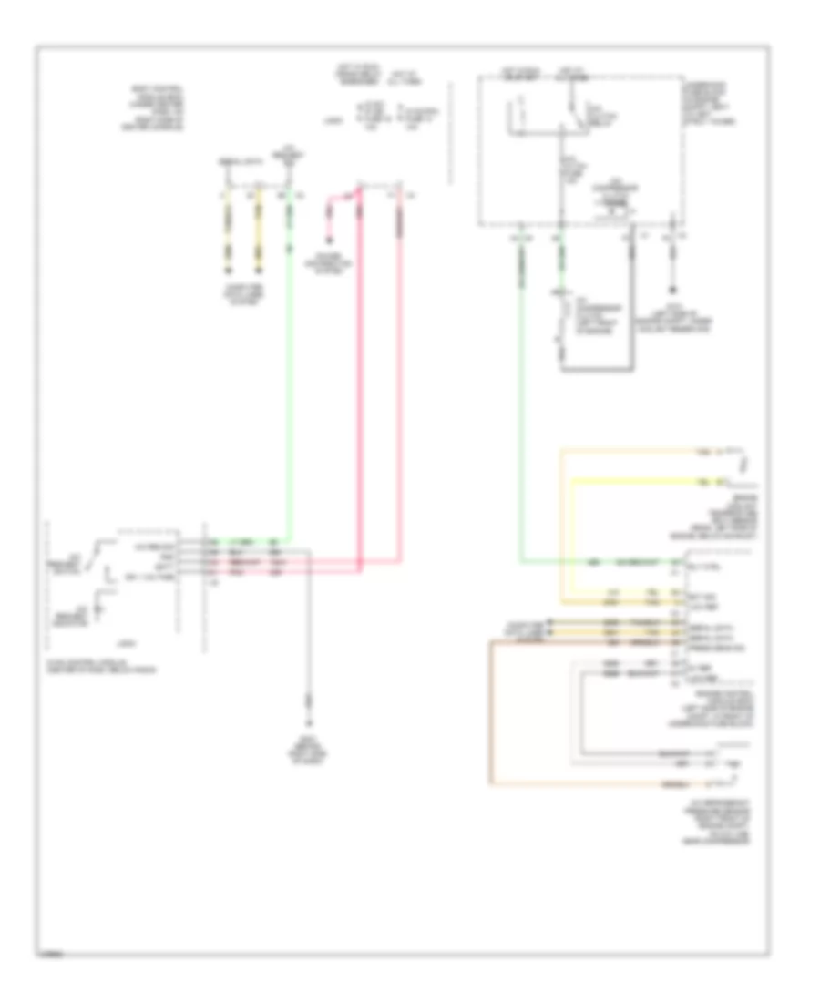
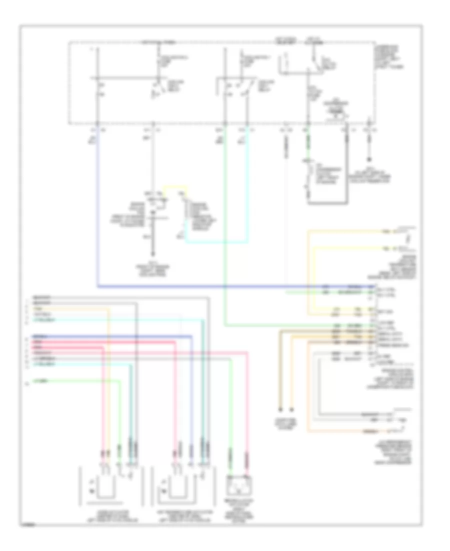
2.4L VIN B, Manual A/C Wiring Diagram (2 of 2) for Pontiac G5 GT 2008
List of elements for 2.4L VIN B, Manual A/C Wiring Diagram (2 of 2) for Pontiac G5 GT 2008:
- 5v ref
- A/c cltch fuse 10a
- A/c cltch relay
- A/c compressor clutch (left front of engine)
- A/c compressor clutch diode
- A/c refrigerant pressure sensor (right front of engine compt, on a/c line, near compressor)
- A11
- A4 x5
- Air temperature actuator (center of dash, left side of hvac module)
- Computer data lines system
- Cooling fan (front of engine compt, attached to radiator)
- Cooling fan 1 fuse 30a
- Cooling fan 1 relay
- Cooling fan 2 fuse 30a
- Cooling fan 2 relay
- E10
- Ect sig
- Engine
- Engine control module (ecm) (left side of engine compt, in front of underhood fuse block)
- Engine coolant temperature (ect) sensor (rear, left side of engine, below exhaust)
- Engine cooling fan resistor (lower left radiator shroud)
- F10
- F2 x3
- G101 (in left side of engine compt, under coolant reservoir)
- G111 (front of engine compt, near cooling fans)
- Hot at all times
- Hot in run or start
- Low ref
- Mode actuator (center of dash, left side of hvac module)
- Pnk
- Press sens sig
- Recirculation actuator (right side of dash, above blower motor)
- Rly ctrl
- Serial data
- Tan
- Underhood fuse block (in engine compt, next to left strut tower)