AIR CONDITIONING
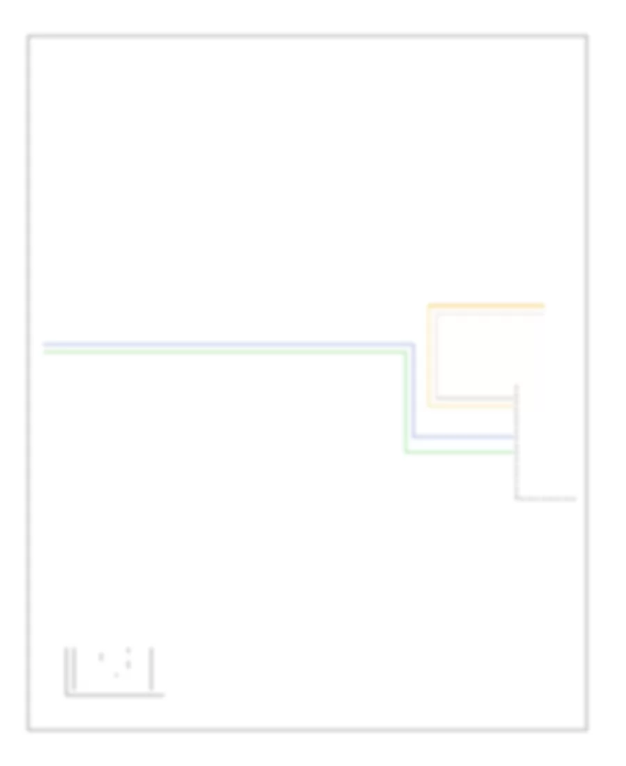
Automatic A/C Wiring Diagram (1 of 2) for Pontiac G6 GT 2007

List of elements for Automatic A/C Wiring Diagram (1 of 2) for Pontiac G6 GT 2007:
- (2.4l/3.6l)
- (3.5l/3.9l)
- (right rear corner of cylinder head) (3.6l) g108
- 5 volt ref
- A/c clu fuse 1 10a
- A/c clutch relay
- A/c compressor clutch (on lower left front of engine, part of a/c compressor)
- A11 c2
- A2 c1
- Air temp dr pos sig
- Ambient air temperature sensor (on left side of front impact bar, behind grille)
- Auto
- Battery positive
- C1 e3
- C3 b9
- Computer data lines system
- Cool fan 1 fuse 17 30a
- Cool fan 2 fuse 18 30a
- Cool ser/par relay
- Cool/ fan 1 relay
- Cool/ fan 2 relay
- Door position sig
- Dr ctrl a
- Dr ctrl b
- E1 c2
- Fresh air ind
- G106 (except 3.6l) (3.5l: on front of engine, at transmission stud, near pnp switch) (2.4l: left rear of engine) (3.9l: left side of engine)
- G108 (3.6l) (right rear corner of cylinder head)
- G201 (under center console, on front support bracket, next to g203)
- Gnd
- High
- Hot at all times
- Hot in run or start
- Hvac control module (in lower center of dash, below radio)
- Ign 3 vol
- Interior lights system
- Left cooling fan (left front of engine compt, mounted to left side of radiator)
- Logic
- Low blower motor switch
- Low ref
- Lower air temperature sensor (under right side of console access panel)
- Mode dr pos sig
- Mode switch
- Off
- Recir door ctrl
- Recirculation ind
- Recirculation switch
- Req sig
- Right cooling fan (right front of engine compt, mounted to right side of radiator)
- Serial data
- Signal
- Tan
- Temperature control switch
- Underhood fuse block (in left side of engine compt)
- Upper air temperature sensor (behind left center of a/c vent)
Automatic A/C Wiring Diagram (2 of 2) for Pontiac G6 GT 2007
List of elements for Automatic A/C Wiring Diagram (2 of 2) for Pontiac G6 GT 2007:
- (or tan)
- 2.4l/3.6l
- 3.5l/3.9l
- 3.6l
- 5v ref
- A/c refrigerant pressure sensor (mounted on a/c line)
- Air temperature actuator
- Ambient air temp sens sig
- Battery positive
- Blower motor (behind right side of dash, in lower right side of hvac case)
- Blower motor control module (on hvac unit)
- Body control module (bcm) (under right side of center console, near dash)
- Clu rly ctrl
- Computer data lines system
- Data link connector (dlc) (on lower left of dash)
- E2 c4
- Ect sens sig
- Engine control module (ecm) (left side of engine compt)
- Engine coolant temperature (ect) sensor (3.5l: mounted in rear cylinder head, below coolant reservoir) (2.4l: right rear of engine) (3.9l: below throttle actuator control module) (3.6l: left side of engine)
- Except 3.6l
- G203 (under center console, on right side of front support bracket, next to g201)
- Gnd
- High spd gmlan
- High spd rly ctrl
- High speed gmlan serial data +
- High speed gmlan serial data -
- Hot at all times
- Hvac ctrl (batt) fuse 10a
- Hvac ctrl (ign) fuse 10a
- Logic
- Low ref
- Low spd rly ctrl
- Low speed gmlan serial data
- Mode actuator (behind right center of dash, on hvac case)
- Recirculation actuator (behind right side of dash, on upper hvac case)
- Req sig
- Run relay
- Run rly ctrl
- Sens sig
- Spd ctrl
- Sply voltage
- Tan
Compressor Wiring Diagram, with Auto A/C for Pontiac G6 GT 2007
List of elements for Compressor Wiring Diagram, with Auto A/C for Pontiac G6 GT 2007:
- (mounted on a/c line) a/c refrigerant pressure sensor
- (on lower left front of engine, part of a/c compressor) a/c compressor clutch
- 2.4l/3.6l
- 3.5l/3.9l
- 5v ref
- A/c clu fuse 1 10a
- A/c clutch relay
- Body control module (bcm) (under right side of center console, near dash)
- C1 e8
- C2 e1
- Clu rly ctrl
- Computer data lines system
- Engine control module (ecm) (left side of engine compt)
- G106 (except 3.6l) (3.5l: on front of engine, at transmission stud, near pnp switch) (2.4l: left rear of engine) (3.9l: left side of engine)
- G108 (3.6l) (right rear corner of cylinder head)
- High spd gmlan
- High speed gmlan serial data
- Hot at all times
- Hot in run or start
- Hvac control module (in lower center of dash, below radio)
- Logic
- Low ref
- Low speed gmlan serial data
- Mode switch
- Sens sig
- Serial data
- Tan
- Temperature control switch
- Underhood fuse block (in left side of engine compt)
Compressor Wiring Diagram, with Manual A/C for Pontiac G6 GT 2007
List of elements for Compressor Wiring Diagram, with Manual A/C for Pontiac G6 GT 2007:
- (mounted on a/c line) a/c refrigerant pressure sensor
- 2.4l/3.6l
- 3.5l/3.9l
- 5v ref
- A/c clu fuse 1 10a
- A/c clutch relay
- A/c compressor clutch (on lower left front of engine, part of a/c compressor)
- A/c req sig
- A/c request ind
- A/c request switch
- Body control module (bcm) (under right side of center console, near dash)
- Clu rly ctrl
- Computer data lines system
- E1 c2
- E8 c1
- Engine control module (ecm) (left side of engine compt)
- G106 (3.5l/3.6l: on front of engine, at transmission stud, near pnp switch) (2.4l: left rear of engine) (3.9l: left side of engine)
- High spd gmlan
- High speed gmlan serial data
- Hot at all times
- Hot in run or start
- Hvac control module (in lower center of dash, below radio)
- Logic
- Low ref
- Low speed gmlan serial data
- Mode switch
- Sens sig
- Tan
- Temperature control switch
- Underhood fuse block (in left side of engine compt)
Manual A/C Wiring Diagram (1 of 2) for Pontiac G6 GT 2007
List of elements for Manual A/C Wiring Diagram (1 of 2) for Pontiac G6 GT 2007:
- (2.4l/3.6l)
- (3.5l/3.9l)
- 5 volt ref
- A/c clu fuse 1 10a
- A/c clutch relay
- A/c compressor clutch (on lower left front of engine, part of a/c compressor)
- A/c req sig
- A/c request ind
- A/c request switch
- A10
- A11
- A11 c2
- A12
- A2 c1
- Air temp dr pos sig
- Ambient air temperature sensor (on left side of front impact bar, behind grille)
- B10
- B11
- B12
- B9 c3
- Batt
- Blower motor resistor assembly (under right side of dash)
- Blower motor switch
- C1 e3
- C2 g
- Cool fan 1 fuse 17 30a
- Cool ser/par relay
- Cool/ fan 1 relay
- Cool/ fan 2 fuse 18 30a
- Cool/ fan 2 relay
- Defog ind
- Defog sw
- Defogger system
- Dr ctrl a
- Dr ctrl b
- E1 c2
- Exterior lights system
- Fresh air ind
- G106 (3.5l/3.6l: on front of engine, at transmission stud, near pnp switch) (2.4l: left rear of engine) (3.9l: left side of engine)
- G106 (except 3.6l) (3.5l: on front of engine, at transmission stud, near pnp switch) (2.4l: left rear of engine) (3.9l: left side of engine)
- G108 (3.6l) (right rear corner of cylinder head)
- G201 (under center console, on front support bracket, next to g203)
- Ground
- High
- Hot at all times
- Hot in run or start
- Hvac control module (in lower center of dash, below radio)
- Ign 3 vol
- Interior lights system
- Left cooling fan (left front of engine compt, mounted to left side of radiator)
- Logic
- Low
- Low ref
- Mode dr pos sig
- Mode switch
- Off
- Park lmp sply vol
- Recirculation ind
- Recirculation switch
- Right cooling fan (right front of engine compt, mounted to right side of radiator)
- Tan
- Temperature control switch
- Underhood fuse block (in left side of engine compt)
Manual A/C Wiring Diagram (2 of 2) for Pontiac G6 GT 2007
List of elements for Manual A/C Wiring Diagram (2 of 2) for Pontiac G6 GT 2007:
- (or tan)
- 2.4l/3.6l
- 3.5l/3.9l
- 3.6l
- 5v ref
- A/c refrigerant pressure sensor (mounted on a/c line)
- A/c req sig
- After blow
- Air temperature actuator
- Ambient air temp sens sig
- Blower motor (behind right side of dash, in lower right side of hvac case)
- Body control module (bcm) (under right side of center console, near dash)
- Clu rly ctrl
- Computer data lines system
- Data link connector (dlc) (on lower left of dash)
- E3 c4
- Ect sens sig
- Engine control module (ecm) (left side of engine compt)
- Engine coolant temperature (ect) sensor (3.5l: mounted in rear cylinder head, below coolant reservoir) (2.4l: right rear of engine) (3.9l: below throttle actuator control module) (3.6l: left side of engine)
- Except 3.6l
- G203 (under center console, on right side of front support bracket, next to g201)
- Ground
- High spd gmlan
- High spd rly ctrl
- High speed gmlan serial data +
- High speed gmlan serial data -
- Hot at all times
- Hvac blower fuse 20a
- Hvac blower high relay
- Hvac ctrl (batt) fuse 10a
- Hvac ctrl (ign) fuse 10a
- Logic
- Low ref
- Low spd rly ctrl
- Low speed gmlan serial data
- Mode actuator (behind right center of dash, on hvac case)
- Recirculation actuator (behind right side of dash, on upper hvac case)
- Run relay
- Run rly ctrl
- Sens sig
- Tan