AIR CONDITIONING
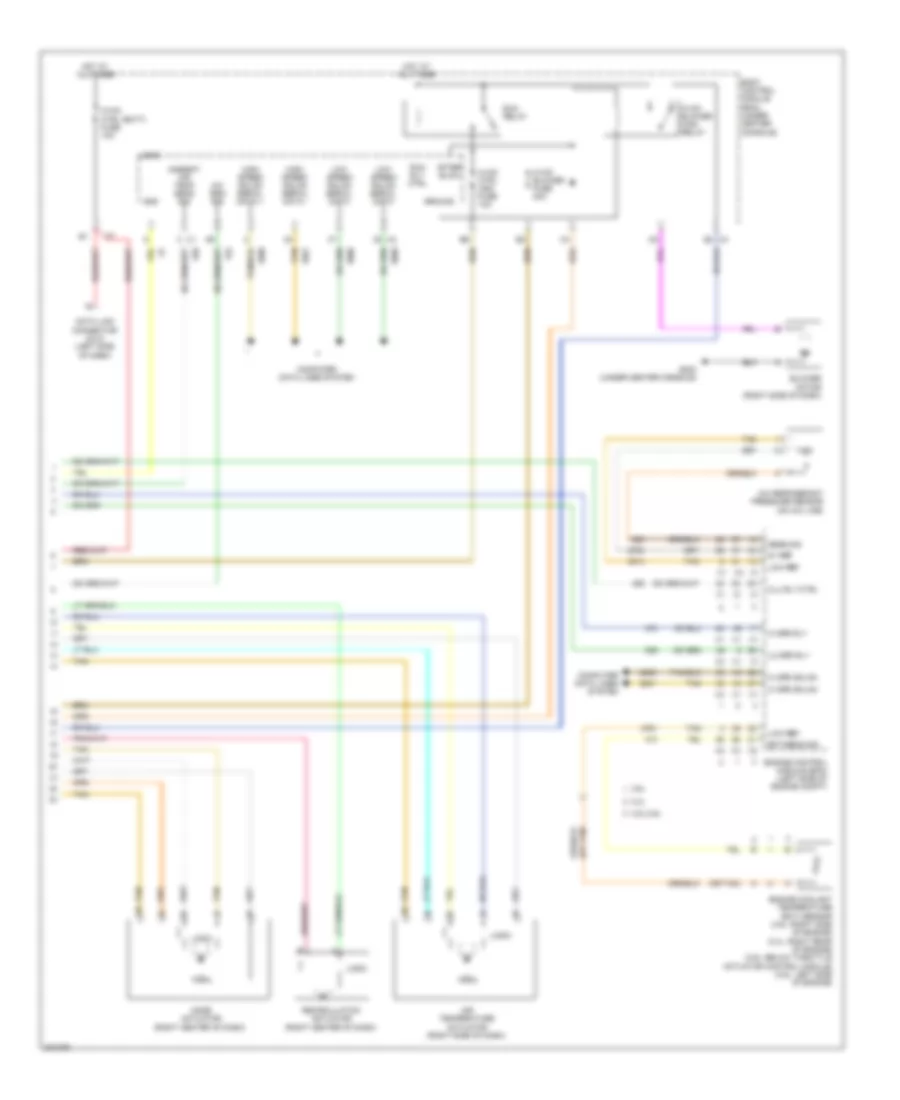
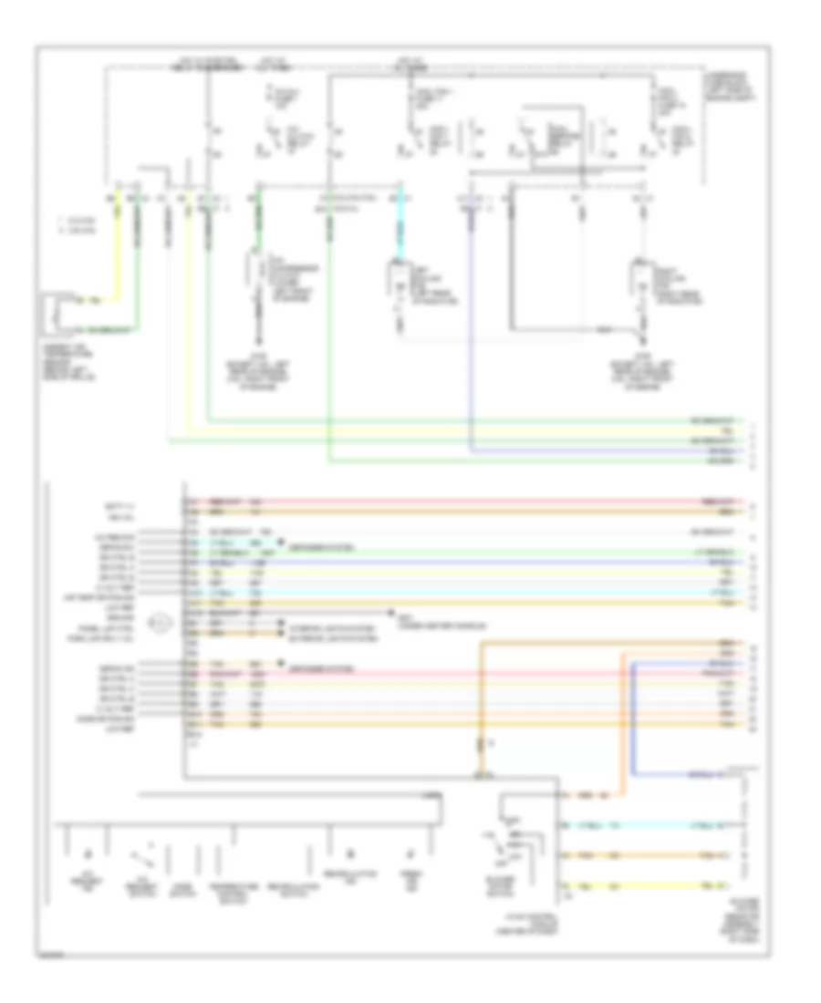
Automatic A/C Wiring Diagram (1 of 2) for Pontiac G6 GXP 2010

List of elements for Automatic A/C Wiring Diagram (1 of 2) for Pontiac G6 GXP 2010:
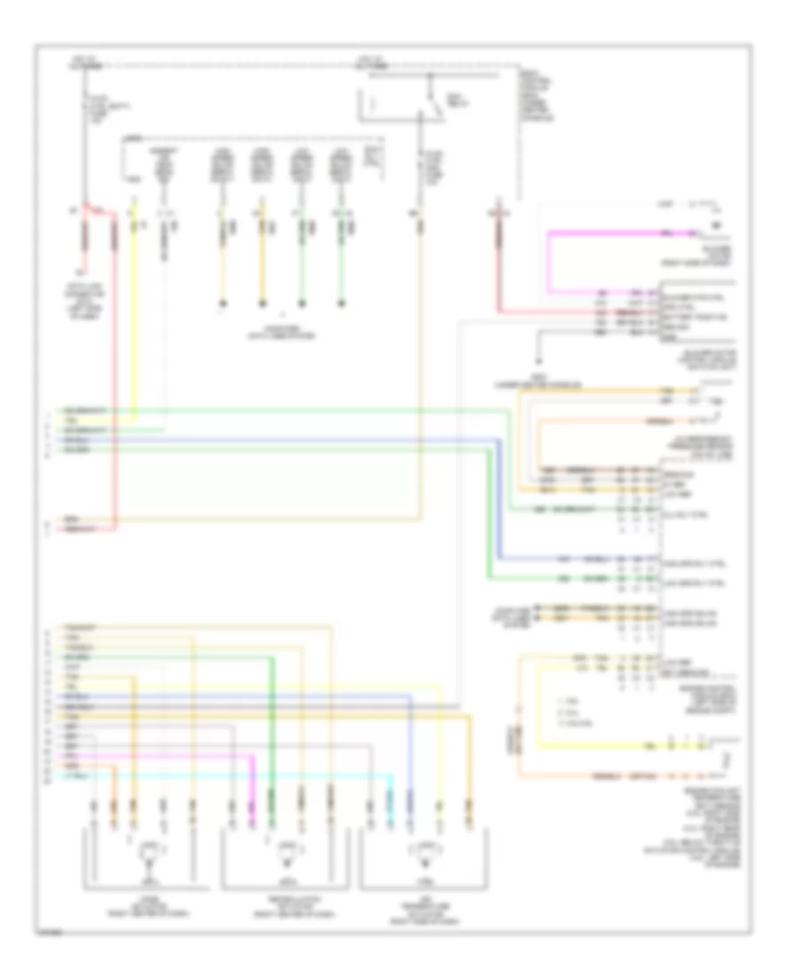
Automatic A/C Wiring Diagram (2 of 2) for Pontiac G6 GXP 2010
List of elements for Automatic A/C Wiring Diagram (2 of 2) for Pontiac G6 GXP 2010:
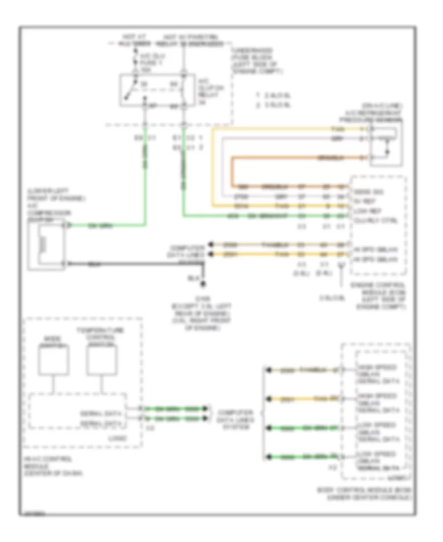
Compressor Wiring Diagram, with Auto A/C for Pontiac G6 GXP 2010
List of elements for Compressor Wiring Diagram, with Auto A/C for Pontiac G6 GXP 2010:
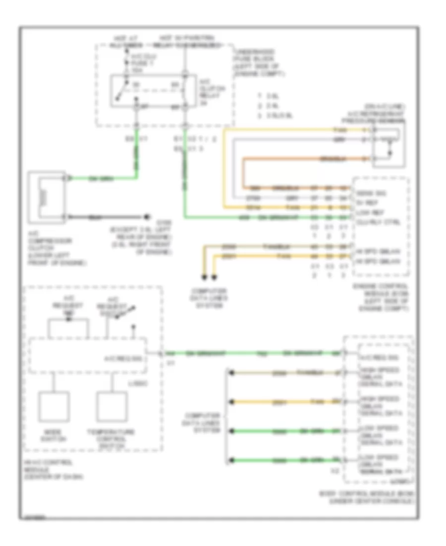
Compressor Wiring Diagram, with Manual A/C for Pontiac G6 GXP 2010
List of elements for Compressor Wiring Diagram, with Manual A/C for Pontiac G6 GXP 2010:
Manual A/C Wiring Diagram (1 of 2) for Pontiac G6 GXP 2010
List of elements for Manual A/C Wiring Diagram (1 of 2) for Pontiac G6 GXP 2010:
Manual A/C Wiring Diagram (2 of 2) for Pontiac G6 GXP 2010
List of elements for Manual A/C Wiring Diagram (2 of 2) for Pontiac G6 GXP 2010: