AIR CONDITIONING
Compressor Wiring Diagram for Pontiac Grand Am GT 2005

List of elements for Compressor Wiring Diagram for Pontiac Grand Am GT 2005:
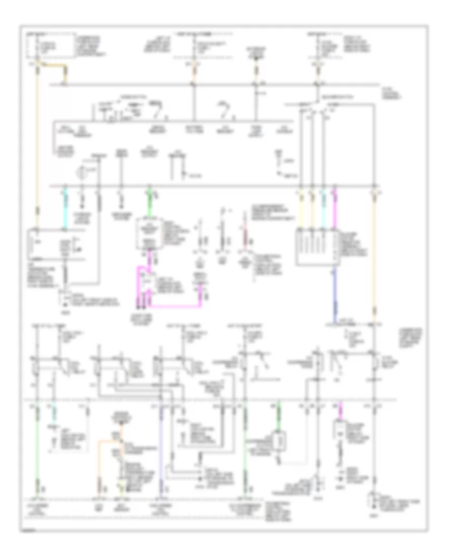
Manual A/C Wiring Diagram for Pontiac Grand Am GT 2005
List of elements for Manual A/C Wiring Diagram for Pontiac Grand Am GT 2005: