AIR CONDITIONING
Compressor Wiring Diagram for Pontiac Grand Am SE 1999

List of elements for Compressor Wiring Diagram for Pontiac Grand Am SE 1999:
- A/c bfc fuse 10a
- A/c clutch diode
- A/c clutch relay
- A/c compressor clutch
- A/c on
- A/c request
- A/c request input
- A/c request output
- Bi-lev
- Body control module (below right side of dash)
- Compressor clutch relay control
- Computer data lines system
- Def
- G103 (l4: lower front of engine) (v6: left side of engine)
- Heat
- Heat/def
- Heater-a/c control assembly
- Hot in on and start
- Lh i/p junction block (below left side of dash)
- Max
- Mode switch
- Powertrain control module (below left side of dash)
- Serial data class 2
- Underhood junction block (in left side of engine compartment on strut tower)
- Vent
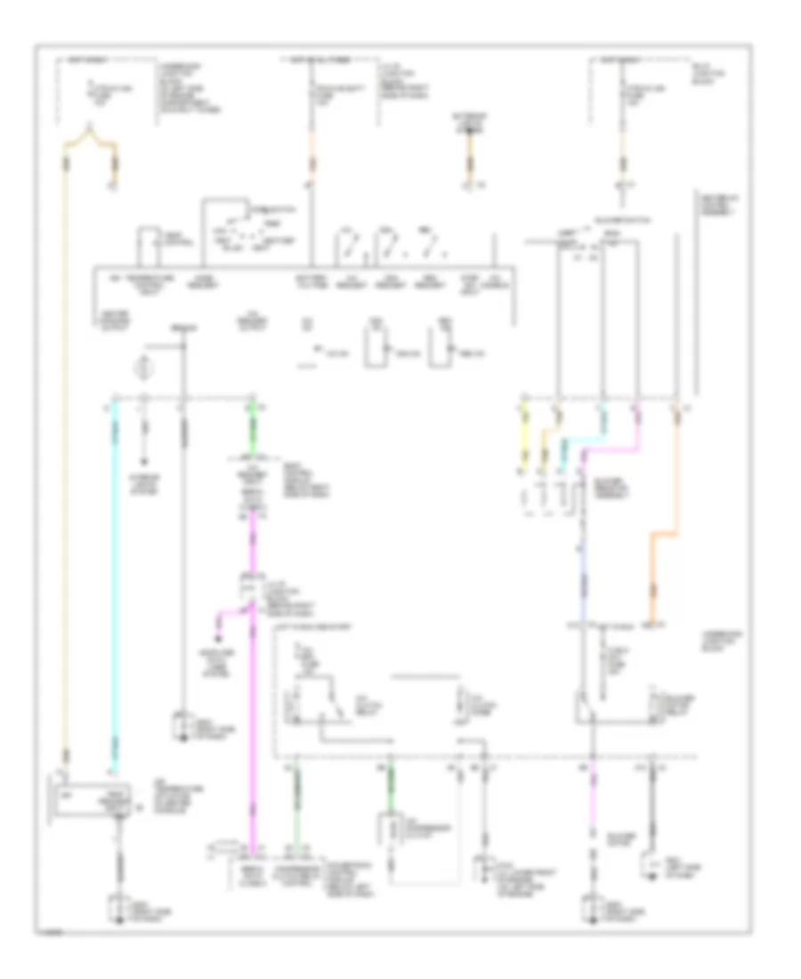
Manual A/C Wiring Diagram for Pontiac Grand Am SE 1999
List of elements for Manual A/C Wiring Diagram for Pontiac Grand Am SE 1999:
- A/c
- A/c bfc fuse 10a
- A/c clutch diode
- A/c clutch relay
- A/c compressor clutch
- A/c disable
- A/c on
- A/c request
- A/c request input
- A/c request output
- A10
- Air temperature actuator (in center console)
- Battery voltage
- Bi-lev
- Blower motor
- Blower motor relay
- Blower resistor assembly
- Blower switch
- Body control module (below right side of dash)
- C10
- Compressor clutch relay control
- Computer data lines system
- Def
- Exterior lights system
- G103 (l4: lower front of engine) (v6: left side of engine)
- G201 (left side of dash)
- G203 (right side of dash)
- G204 (right side of dash)
- Gnd
- Ground
- Heat
- Heat/def
- Heater command output
- Heater-a/c control assembly
- Hi blo mot fuse 30a
- High
- Hot at all times
- Hot in run
- Hot in run and start
- Htr-a/c ign fuse 10a
- Ign
- Interior lights system
- Ipc/hvac batt fuse 10a
- Lh i/p junction block (behind right side of dash)
- Low
- Max
- Mode request
- Mode switch
- Off
- Osa
- Osa on
- Osa request
- Powertrain control module (below left side of dash)
- Rec
- Rec on
- Rec request
- Rh ip junction block
- Serial data class 2
- Step dim input
- Tan
- Temp control
- Temp request input
- Temperature control input
- Underhood junction block
- Underhood junction block (in left side of engine compartment, on strut tower)
- Vent