AIR CONDITIONING
Compressor Wiring Diagram for Pontiac Grand Prix GT 2004

List of elements for Compressor Wiring Diagram for Pontiac Grand Prix GT 2004:
- (right side of upper left footwell) sp205
- 5 volt ref
- A/c clu diode
- A/c clutch fuse 10a
- A/c comp control
- A/c comp relay
- A/c compressor clutch (on front of a/c compressor)
- A/c press signal
- A/c refrigerant pressure sensor (on left side of engine compt, on accumulator)
- A/c request ind
- A/c request switch
- Battery
- G113 (lower right front of engine, on transaxle stud, near starter)
- G202 (right side upper left footwell)
- Gnd
- Hot at all times
- Hot in run or start
- Hvac class 2
- Hvac control module (center of dash)
- Hvac fuse 10a
- I/p fuse block (behind right side of dash, in glove box opening)
- Logic
- Low ref
- Pcm class 2
- Powertrain control module (pcm) (left front side of engine compt, in air cleaner assembly)
- S211 (i/p wiring harness, behind center of dash, 11 cm from data link connector)
- Underhood fuse block (mounted to right strut tower)
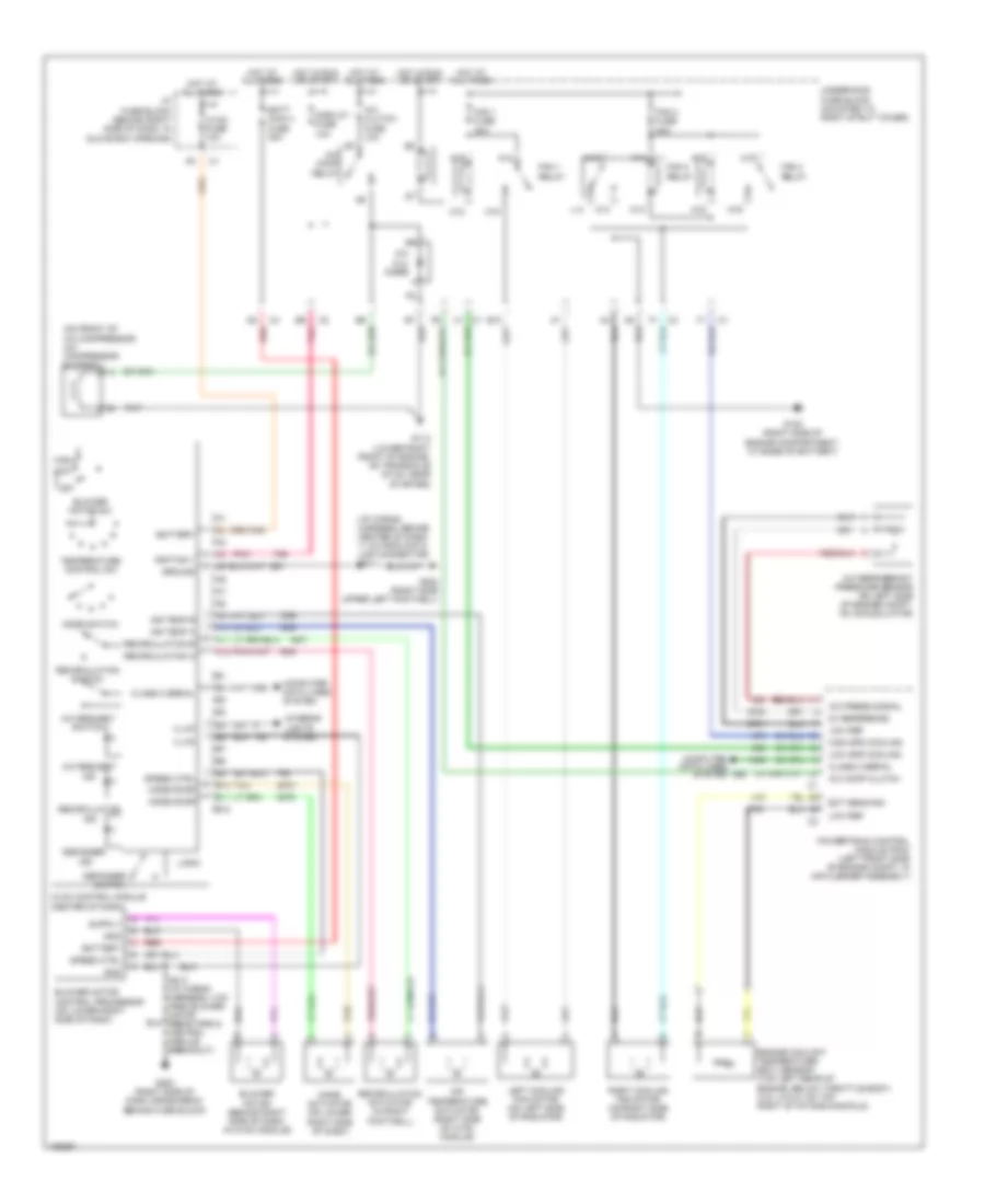
Manual A/C Wiring Diagram for Pontiac Grand Prix GT 2004
List of elements for Manual A/C Wiring Diagram for Pontiac Grand Prix GT 2004:
- (i/p wiring harness, behind center of dash, 11 cm from data link connector) s211
- (on front of a/c compressor) a/c compressor clutch
- 5v reference
- A/c clu diode
- A/c clutch fuse 10a
- A/c comp clutch
- A/c comp relay
- A/c press signal
- A/c refrigerant pressure sensor (on left side of engine compt, on accumulator)
- A/c request ind
- A/c request switch
- A10
- A11
- A12
- A18
- A19
- Air temp a
- Air temp b
- Air temperature actuator (right side of hvac module)
- B10
- B11
- B12
- Batt main 4 fuse 30a
- Battery
- Blower motor (behind right side of dash, in hvac module)
- Blower motor control processor (on lower right side of dash)
- Blower motor sw
- C18
- C19
- Class 2 serial
- Computer data lines system
- Defogger
- Defogger switch
- Display fuse 10a
- E10
- Ect sens sig
- Engine coolant temperature (ect) sensor (top left rear of engine, below throttle body) (3.8l (vin 2): on top right of intake manifold)
- Fan 1 fuse 30a
- Fan 1 relay
- Fan 2 fuse 30a
- Fan 2 relay
- Fan 3 relay
- G100 (right side of engine compartment, at base of battery)
- G113 (lower right front of engine, on transaxle stud, near starter)
- G200 (right side of dash cross beam, behind fuse block)
- G202 (right side upper left footwell)
- Gnd
- Ground
- High
- High spd cooling
- Hot at all times
- Hot in run or start
- Hvac control module (center of dash)
- Hvac fuse 10a
- I/p fuse block (behind right side of dash, in glove box opening)
- Ignition 1
- Illum
- Ind
- Interior lights system
- K14
- K15
- K18
- K19
- L14
- Left cooling fan motor (on left side of radiator)
- Logic
- Low
- Low ref
- Low spd cooling
- M14
- M15
- M18
- M19
- Mode actuator (on lower right side of dash)
- Mode door
- Mode switch
- Off
- Pnk
- Powertrain control module (pcm) (left front side of engine compt, in air cleaner assembly)
- Recirculation
- Recirculation a
- Recirculation actuator (in right footwell)
- Recirculation b
- Recirculation switch
- Red
- Right cooling fan motor (on right side of radiator)
- S213 (i/p wiring harness, 4 cm from blower motor resistors & control module breakout)
- Speed ctrl
- Tan
- Temperature control sw
- Underhood fuse block (mounted to right strut tower)