AIR CONDITIONING
Compressor Wiring Diagram for Pontiac GTO 2005

List of elements for Compressor Wiring Diagram for Pontiac GTO 2005:
- A/c
- A/c compressor clutch
- A/c compressor clutch relay (micro)
- A/c ind
- A/c refrigerant pressure sensor (left front corner of engine compt)
- A/c request
- A/c switch
- Behind under hood fuse panel)
- Body control module (bcm) (below right side of dash)
- Clu rly ctrl
- Clutch
- Compressor
- Computer data lines system
- Diode
- Engine sensors fuse 15a
- G105 (rear of engine, near left valve cover, attached to block)
- Heated rear window, hvac & instruments fuse 7.5a
- Hot in run or start
- Hvac control assembly (center of dash, under radio)
- Instrument cluster)
- Instrument panel fuse block (below left end of dash)
- Low ref
- Pnk
- Powertrain control module (pcm) (left side of engine compt)
- Press sens sig
- S111 (top of right strut mount,
- S130 (730mm from engine ground)
- S134 (510 mm from a/c compressor diode)
- Serial data
- Tan
- Uart serial data
- Underhood fuse block (on right side of engine compt)
- Vol
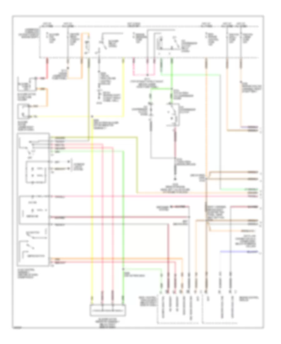
Manual A/C Wiring Diagram (1 of 2) for Pontiac GTO 2005
List of elements for Manual A/C Wiring Diagram (1 of 2) for Pontiac GTO 2005:
- (295 mm from c206) s105
- A/c compressor clutch
- A/c compressor clutch diode
- A/c compressor clutch relay (micro)
- A/c ind
- A/c request
- A/c switch
- Bat
- Bcm/ engine control fuse 15a
- Blower fan fuse 40a
- Blower fuse 30a
- Blower motor (under right side of dash)
- Blower motor inline fuse holder
- Blower motor resistor assembly (below right side of dash)
- Blower relay (micro)
- Blr mtr low ctrl
- Body control module (bcm) (below right side of dash)
- Data link connector (dlc) (under dash, below steering column)
- Defog ind
- Defog switch
- Defogger system
- Engine control module
- Engine sensors fuse 15a
- G102
- G105 (rear of engine, near left valve cover, attached to block)
- Heated rear window fuse 30a
- High spd cool fan
- Hot at all times
- Hot in run or start
- Hvac control assembly (center of dash, under radio)
- Interior lights system
- Low spd cool fan
- Off
- Panel, near seat bottom) s106
- Pnk
- Rad fan large fuse 30a
- Rad fan small fuse 30a
- Rear defog sw
- Red
- S111 (top of right strut mount, behind under hood fuse panel)
- S114 (inside underhood fuse panel)
- S134 (510 mm from a/c compressor diode)
- S165 (engine cooling harness, front of battery)
- S255 (355 mm from blower motor resistor assembly)
- S256 (335 mm from bcm)
- S257 (behind bcm)
- Sec rear defog sw
- Sp100 (engine compt in right front wheel well)
- Underhood fuse block (on right side of engine compt)
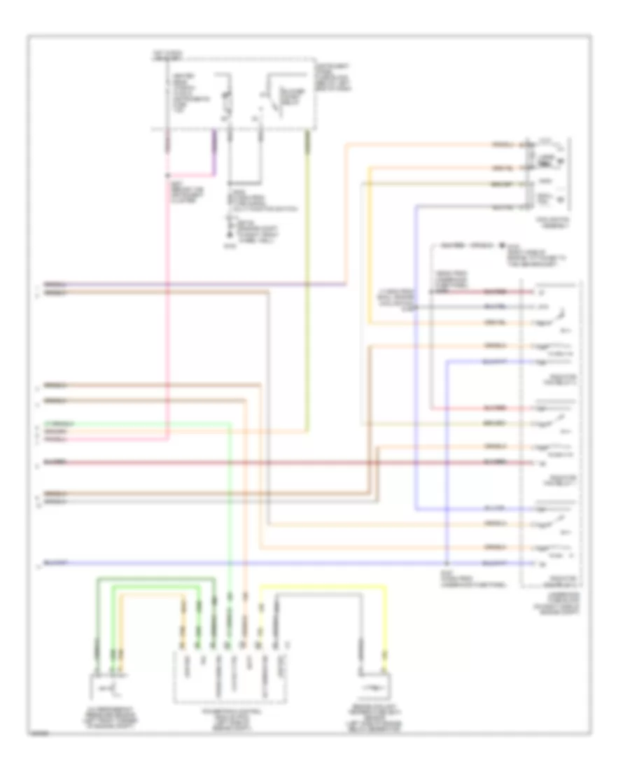
Manual A/C Wiring Diagram (2 of 2) for Pontiac GTO 2005
List of elements for Manual A/C Wiring Diagram (2 of 2) for Pontiac GTO 2005:
- (1135mm from small engine cooling fan) s156
- (360mm from underhood fuse panel) s239
- 87a
- A/c refrigerant pressure sensor (left front corner of engine compt)
- Batt
- Blower inhibit relay
- Clu rly ctrl
- Cooling fan assembly
- Ect sensor sig
- Engine coolant temperature (ect) sensor (left side of engine, below generator)
- G102
- G103 (right side of engine, attached to the abs bracket)
- Heated rear window, hvac & instruments fuse 7.5a
- Hot in run or start
- Instrument panel fuse block (below left end of dash)
- Large fan
- Low ref
- Powertrain control module (pcm) (left side of engine compt)
- Press sens sig
- Radiator fan relay 1
- Radiator fan relay 2
- Radiator fan relay 3
- S157 (275mm from underhood fuse panel)
- S207 (behind the instrument cluster)
- Small fan
- Sp100 (engine compt in right front wheel well)
- Tan
- Underhood fuse block (on right side of engine compt)
- Vol