AIR CONDITIONING
Compressor Wiring Diagram for Pontiac Montana SV6 2005

List of elements for Compressor Wiring Diagram for Pontiac Montana SV6 2005:
- (at engine to transmission stud)
- +5v reference
- A/c compressor clutch
- A/c cltch fuse 6 10a
- A/c cltch relay
- A/c press signal
- A/c refrigerant pressure sensor (on high pressure hose, near high pressure hose connection to a/c compressor)
- A/c request
- A/c request ind cntrl
- A/c request switch
- Class 2 data
- Comp control
- Computer data lines system
- Diode 3
- G115
- Hot in run
- Hot in run, bulb test or start
- Hvac control module (in dash center trim panel, beneath radio)
- Ign
- Ind
- Logic
- Low ref
- Powertrain control module (pcm) (left side of engine compt, in air cleaner assembly)
- Underhood fuse block (in underhood compt, above right front wheel well)
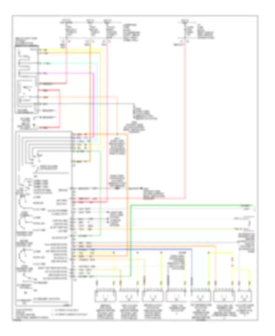
Manual A/C Wiring Diagram (1 of 2) for Pontiac Montana SV6 2005
List of elements for Manual A/C Wiring Diagram (1 of 2) for Pontiac Montana SV6 2005:
- (below right side of dash) blower motor resistor assembly
- (dash harn, main bundle 9 cm from breakout for app sensor) s255
- (dash harn, main bundle, 9 cm from breakout for vent & floor actuator)
- 5 volt ref
- A/c request
- A/c request ind cntrl
- A/c request switch
- Air temp dr cntrl
- Air temperature actuator/ left air temperature actuator (behind center of dash)
- Aux
- Aux air cntrl
- Aux blwr motor sw
- Aux blwr spd cntrl
- Aux blwr speed
- Aux mode dr cntrl
- Auxiliary air temperature actuator (behind left rear interior body panel)
- Auxiliary mode actuator (in rear hvac module)
- Battery
- Blower motor (below right side of dash)
- Blower motor relay
- Blwr sw hi
- Blwr sw off
- Class 2 data
- Clstr/ hvac fuse 8 10a
- Cntrl sig
- Computer data lines system
- Def door cntrl
- Defrost actuator (behind center of dash, left side of front hvac module)
- Door cntrl
- Driver temperature control sw
- Evap temp sig
- Evaporative temperature sensor (in front hvac module, mounted to evaporator core)
- Front blower motor switch
- Frt blwr hi fuse 34 40a
- Frt/ blwr fuse 27 25a
- G200 (on right side of dash support beam, above dash compart)
- Ground
- Hot at all times
- Hot in run
- Hvac control module (in dash center trim panel, beneath radio)
- Hvac/ rpa/ cruise fuse 17 10a
- I/p fuse block (right side of dash, behind access panel)
- Ign
- Ignition 1
- Ind
- Interior lights system
- Lamp dim grd
- Lamp dim sig
- Lo ref
- Logic
- Low ref
- Mode sig
- Mode switch
- Motor off req hvac aux cntrl
- Off
- Pass temperature control sw
- Pnk
- Rec dr cntrl
- Recirculation actuator (above blower motor, right side of front hvac module)
- Red
- Right air temp dr cntrl
- Right air temperature actuator
- S246 (dash harn, 12.5 cm from breakout for recirc actuator)
- S253
- S271 (dash harn, behind radio, 20 cm from main bundle toward right side of dash)
- Speed 1 req
- Speed 3 req speed 2 req
- Tan
- Temperature control sw
- Underhood fuse block (in underhood compt, above right front wheel well)
- Vent & floor actuator (behind center of dash, left side of front hvac module)
- Vnt & flr dr cntrl
- W/ front & rear hvac only
- W/ front hvac only
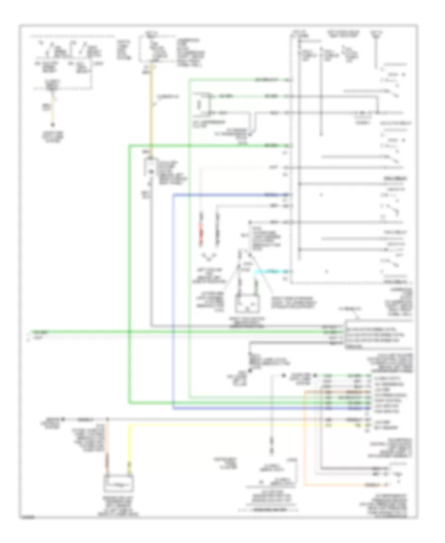
Manual A/C Wiring Diagram (2 of 2) for Pontiac Montana SV6 2005
List of elements for Manual A/C Wiring Diagram (2 of 2) for Pontiac Montana SV6 2005:
- (at engine to transmission stud)
- (in forward lamp harness, 10 cm from breakout for c104)
- (right side of engine compt, on upper front of radiator support)
- +5v reference
- A/c compressor clutch
- A/c cltch fuse 6 10a
- A/c cltch relay
- A/c off for engine protection engine coolant hot
- A/c press signal
- A/c refrigerant pressure sensor (on high pressure hose, near high pressure hose connection to a/c compressor)
- Aux blwr motor speed cntrl
- Aux blwr motor speed sig
- Aux fan speed select
- Aux temp select
- Auxiliary blower motor (behind left rear interior body panel)
- Auxiliary blower motor control module (in rear hvac module, behind left rear interior body panel)
- Blwr motor speed cntrl
- Class 2 data
- Class 2 serial data
- Comp control
- Computer data lines system
- Digital video disc (dvd) player
- Diode 3
- Ect sensor
- Engine controls system
- Engine coolant temperature (ect) sensor (in left side of rear cylinder head)
- Fan 1 fuse 29 30a
- Fan 1 relay
- Fan 2 fuse 33 40a
- Fan 2 relay
- Fan 3 relay
- Fan speed switch
- G100
- G115
- G401 (on lower left "d" pillar)
- Ground
- High spd fan
- Hot at all times
- Hot in run
- Hot in run, bulb test or start
- Ign
- Instrument panel cluster
- Left cooling fan (behind left side of radiator)
- Logic
- Low ref
- Low spd fan
- Message center
- Powertrain control module (pcm) (left side of engine compt, in air cleaner assembly)
- Red
- Right cooling fan (behind right side of radiator)
- Rr blwr/ 110vac fuse 26 25a
- S102 (in forward lamp harness, 6.5 cm from breakout for g100)
- S106
- S140 (in fuel injector harn, 4 cm from breakout for fuel injector 2 toward fuel injector 3)
- Temp select switch
- Underhood fuse block (in underhood compt, above right front wheel well)
- W/ rear a/c