AIR CONDITIONING
Compressor Wiring Diagram for Pontiac Sunfire SE 1999

List of elements for Compressor Wiring Diagram for Pontiac Sunfire SE 1999:
- (engine harn, 20-23 cm from a/c comp clutch connector)
- (hvac harness, behind
- +5v
- A/c clutch diode
- A/c compressor clutch
- A/c compressor clutch relay (in engine compt fuse/relay center)
- A/c fuse 10a
- A/c on switch
- A/c refrigerant pressure sensor (right front corner of engine compt, on refrigerant line)
- B10
- B11
- Bi-lv
- Blend
- Center of dash)
- Chevy
- Data line
- Def
- Engine compartment fuse/relay center
- Erls fuse 10a
- Fuse block
- G112 (left side of engine)
- Heater-a/c and rear defogger control assembly
- Hot at all times
- Hot in run
- Hot in run, bulb test or start
- Htr
- Hvac fuse 10a
- Instrument cluster
- Mode switch
- Off
- Pnk
- Pont
- Powertrain control module (pcm) (on right front of engine compartment)
- Recir
- Relay ctrl
- S101 (engine harn 28-33 cm from cooling fan motor connector)
- S107 (engine harn, 34 cm from engine compt fuse/relay center)
- S111
- S125
- S233
- S277 (i/p harn, lower left of dash)
- Sensor ground
- Sensor input
- Solid state
- Tan
- Vent
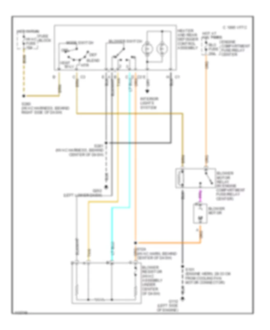
Heater Wiring Diagram for Pontiac Sunfire SE 1999
List of elements for Heater Wiring Diagram for Pontiac Sunfire SE 1999:
- (hvac harn, behind center of dash)
- B tan
- Bi-lv
- Blend
- Blo fuse 30a
- Blower motor
- Blower motor relay (in engine compartment fuse/relay center)
- Blower resistor (hvac assembly under center of dash)
- Blower switch
- C 1995 vftc
- Def
- Engine compartment fuse/relay center
- Fuse block
- G112 (left side of engine)
- G202 (left lower dash)
- Heater and rear defogger control assembly
- Hot at all times
- Hot in run
- Htr
- Hvac fuse 10a
- Interior lights system
- Mode switch
- Off
- S101 (engine hern, 28-33 cm from cooling fan motor connector)
- S280 (hvac harness, behind right side of dash)
- S281 (hvac harness, behind center of dash)
- Tan
- Vent
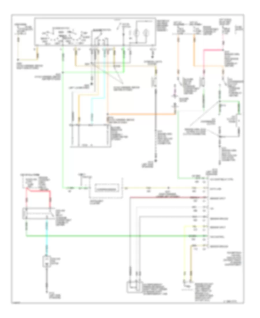
Manual A/C Wiring Diagram for Pontiac Sunfire SE 1999
List of elements for Manual A/C Wiring Diagram for Pontiac Sunfire SE 1999:
- (engine harn, 20-23 cm from a/c comp clutch connector)
- (hvac harness, behind center of dash)
- +5v
- A/c clutch diode
- A/c comp relay ctrl
- A/c compressor clutch
- A/c compressor clutch relay (in engine compt fuse/relay center)
- A/c fuse 10a
- A/c on switch
- A/c refrigerant pressure sensor (right front corner of engine compt, on refrigerant line)
- B tan
- B10
- B11
- Bi-lv
- Blend
- Blo fuse 30a
- Blower motor
- Blower motor relay (in engine compartment fuse/relay center)
- Blower resistor (hvac assembly under center of dash)
- Blower switch
- C 1995 vftc
- Chevy
- Cooling fan fuse 30a
- Cooling fan motor
- Cooling fan relay (in engine compartment fuse/relay center)
- Data line
- Def
- Engine compart- ment fuse/ relay center
- Engine compartment fuse/relay center
- Engine coolant temperature (ect) sensor (left front of engine) (2.2l) (on rear of eng, near coolant outlet) (2.4l)
- Erls fuse 10a
- Fan control
- Fuse block
- G112 (left side of engine)
- G112 (left side of engine)
- G202 (left lower dash)
- Heater-a/c and rear defogger control assembly
- Hot at all times
- Hot in run
- Hot in run, bulb test or start
- Htr
- Hvac fuse 10a
- Instrument cluster
- Interior lights
- Microprocessor
- Mode switch
- Off
- Pnk
- Pontiac
- Powertrain control module (pcm) (on right front of engine compartment)
- Recir
- Red
- S101 (engine harn 28-33 cm from cooling fan motor connector)
- S107 (engine harn, 34 cm from engine compt fuse/relay center)
- S111
- S125
- S233 (hvac harness, behind center of dash)
- S277 (dash harness, lower left of dash)
- S280 (hvac harness, behind right side of dash)
- S281
- Sensor ground
- Sensor input
- System
- Tan
- Vent