AIR CONDITIONING
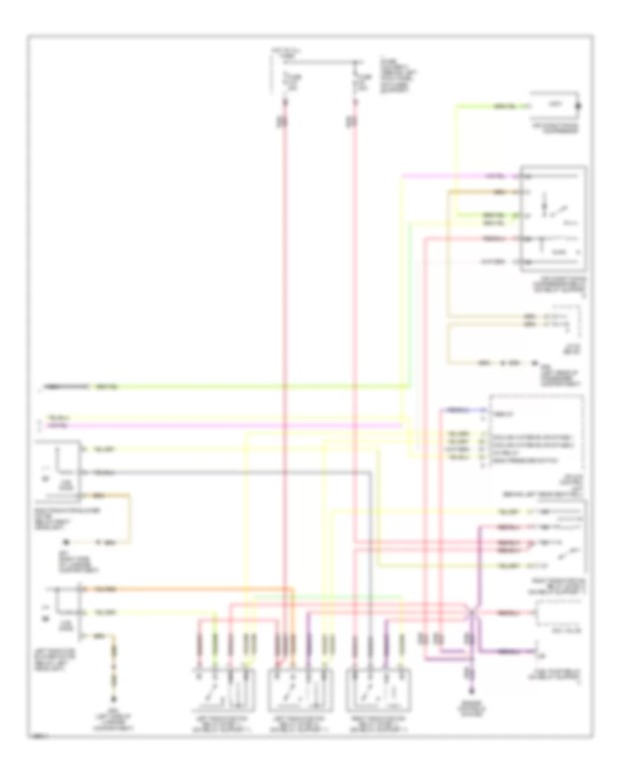
Automatic A/C Wiring Diagram, Early Production (1 of 2) for Porsche 911 GT3 2004

List of elements for Automatic A/C Wiring Diagram, Early Production (1 of 2) for Porsche 911 GT3 2004:
- (2005) (2004)
- +5v/10 ma
- A/c pressure switch (at front of air cleaner)
- Actuation fan
- Air inlet outside sensor
- Can komfort high
- Can komfort low
- Central flap check sig
- Circulating air/outside air
- Climatronic control unit
- Close outside air
- Compressor voltage
- Computer data lines system
- Cool
- Defrost
- Fan
- Fan return
- Fan return (+)
- Final stage
- Footwell
- Footwell output sensor
- Footwell/defrost
- Footwell/defrost flap motor (on heating/ air conditioning unit)
- Footwell/defrost signal
- Fuse b1 15a
- Fuse c7 7.5a
- Fuse d6 30a
- Fuse e7 7.5a
- Fuse holder b (behind left kick panel, on fuses support)
- Fuse holder c (behind left kick panel, on fuses support)
- Fuse holder d (behind left kick panel, on fuses support)
- Fuse holder e (behind left kick panel, on fuses support)
- Gp3/1 (left center side of support frame)
- Gp4 (center of support frame)
- Heater relay (on relay support 1)
- High/low pressure
- Hot
- Hot at all times
- Hot in acc or run
- Hot in run or start
- Inside temp sensor
- Inside temperature sensor blower
- J/c (bs 9/2)
- Mean pressure
- Middle level
- Nca
- Output sensor footwell
- Output temp sensor
- Outside air central flap motor (on heating/ air conditioning unit)
- Recirculation valve central flap motor (on heating/ air conditioning unit)
- Sensor ground
- Temperature flap motor (on heating/ air conditioning unit)
- Temperature flap signal
- Term 15
- Term 30
- Term 31
- Terminal xe relay (on relay support 1)
- Up outside air
Automatic A/C Wiring Diagram, Early Production (2 of 2) for Porsche 911 GT3 2004
List of elements for Automatic A/C Wiring Diagram, Early Production (2 of 2) for Porsche 911 GT3 2004:
- 0.55 ohms
- A/c relay
- Aav valve
- Air conditioning compressor
- Air conditioning compressor relay (on relay support 2)
- Cooling water blwr stage 1
- Cooling water blwr stage 2
- Engine controls system
- Fuel pump relay (on relay support 1)
- Fuse c10 40a
- Fuse c8 40a
- Fuse holder c (behind left kick panel, on fuses support)
- Gp1 (right side of luggage compartment)
- Gp2 (left side of luggage compartment)
- Gp8 (left rear of passenger compartment)
- Hot at all times
- J/c 22 (bs 22)
- Left radiator blower motor (below left headlight)
- Left radiator fan relay (step 1) (on relay support 1)
- Left radiator fan relay (step 2) (on relay support 1)
- Mean pressure switch
- Mfi & di control unit (behind left rear seatwell)
- Nca
- Right radiator blower motor (below right headlight)
- Right radiator fan relay (step 1) (on relay support 1)
- Right radiator fan relay (step 2) (on relay support 1)
- Term 87