AIR CONDITIONING
Automatic A/C Wiring Diagram (1 of 2) for Saab 9-5 Aero 2008

List of elements for Automatic A/C Wiring Diagram (1 of 2) for Saab 9-5 Aero 2008:
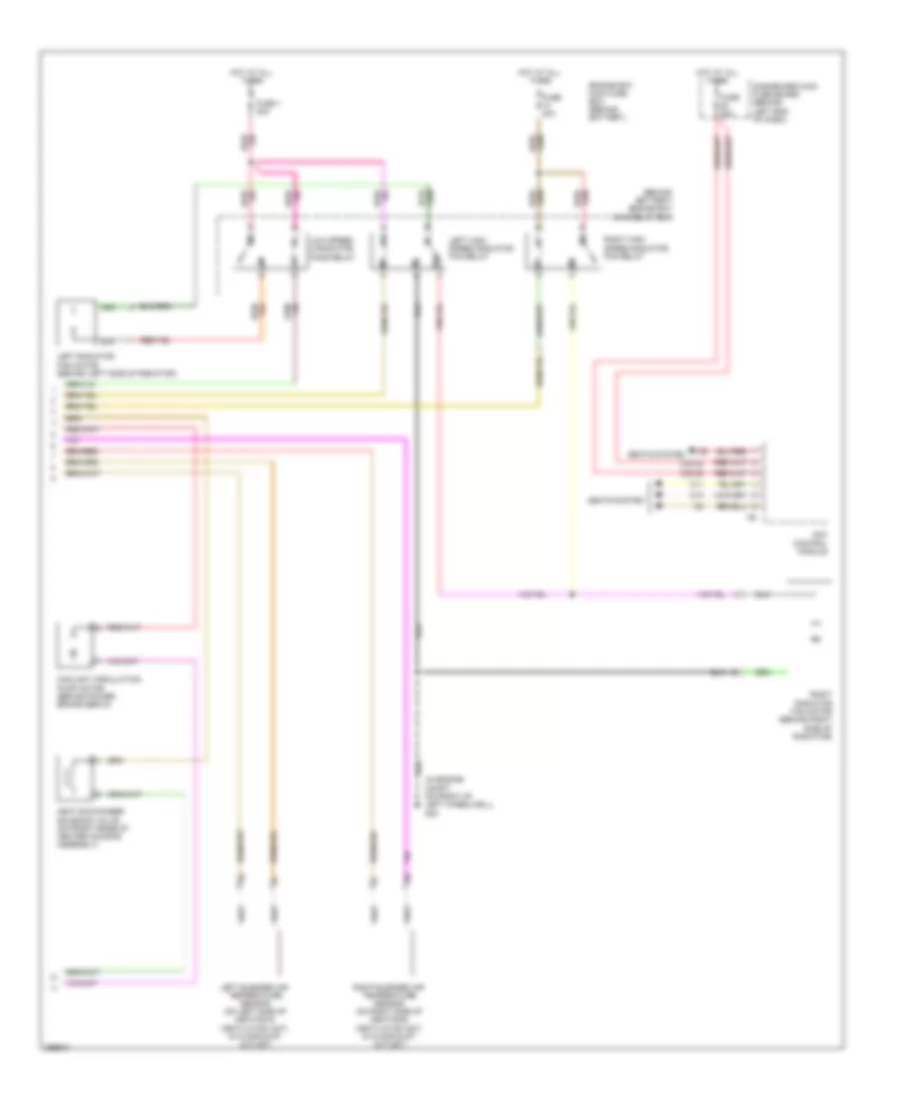
Automatic A/C Wiring Diagram (2 of 2) for Saab 9-5 Aero 2008
List of elements for Automatic A/C Wiring Diagram (2 of 2) for Saab 9-5 Aero 2008: