AIR CONDITIONING
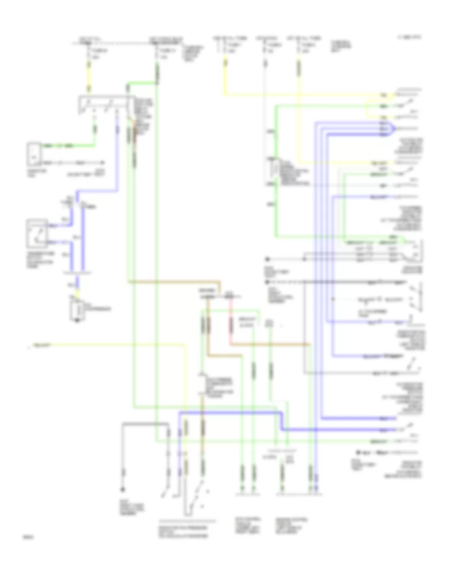
A/C Wiring Diagram (1 of 2) for Saab 9000 CDE 1994

List of elements for A/C Wiring Diagram (1 of 2) for Saab 9000 CDE 1994:
- (left dashboard reinforcing member)
- (on battery tray) g102
- Air distribution damper motor (inside glove box)
- Air mix transmitter (under servo motor unit)
- Automatic climate control unit
- C 1995 vftc
- Diagnostic test socket (below right front seat)
- Edu trip computer
- Fuse 10a
- Fuse 30a
- Fuse 5a
- Fuse box (behind glove box)
- G200
- G300 (left front seat member)
- G304 (under left rear seat)
- Hot at all times
- Hot in run
- Hot in run, bulb test or start
- Interior lights system
- Interior temperature sensor (in panel between steering wheel and console)
- Left door fan motor
- Outside temperature sensor (behind left of front spoiler)
- Rear defogger system
- Recirculation damper motor (right side of engine compartment)
- Red
- Right door fan motor
- Scc trip computer (center of fascia)
- Sun sensor (center of fascia)
- Temperature control damper motor (inside glove box)
- Ventilation fan
- Ventilation fan speed control (in evaporator housing, behind bulkhead)
A/C Wiring Diagram (2 of 2) for Saab 9000 CDE 1994
List of elements for A/C Wiring Diagram (2 of 2) for Saab 9000 CDE 1994:
- (in fuse box, behind glove box)
- (in fuse box, in engine bay)
- (under right side of radiator)
- 10a
- 30a
- A/c compressor
- A/c cooling fan relay (in fuse box in engine bay)
- A/c radiator pressure switch (w/ two-speed fans)
- All others
- Anti-freeze thermostat (on evaporator casing)
- C 1995 vftc
- Cooling fan time delay relay (in fuse box behind glove box)
- Engine control module (left side of bulkhead)
- Ets control module (under left front seat)
- Fuse 13
- Fuse 20
- Fuse 6
- Fuse 7
- Fuse 8
- Fuse box (behind glove box)
- Fuse box (in engine bay)
- G101 (right structural member)
- G102 (on battery tray)
- G107 (right hand structural member)
- Hot at all times
- Hot in run
- Hot in run, bulb test or start
- Nca
- Radiator fan
- Radiator fan motor
- Radiator fan pressure switch (on accumulator/dryer)
- Radiator fan relay
- Radiator fan thermostatic switch (left side of radiator)
- Temperature switch (on radiator hose)
- Turbo a/t
- Two- speed radiator fan resistor (beside radiator fan)
- Two-speed radiator fan relay (w/ two-speed fans)
- W/ ets
- W/ two-speed fans
- W/o ets