AIR CONDITIONING
2.2L VIN D
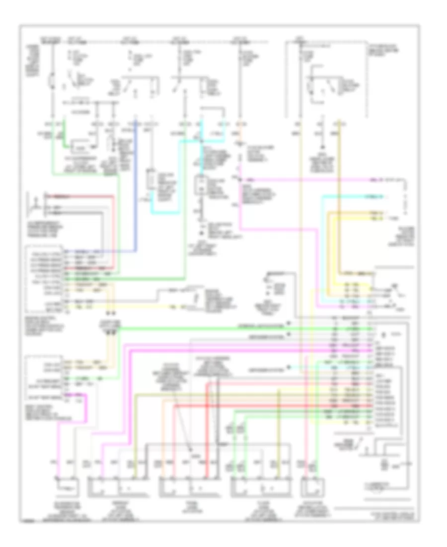
2.2L VIN D, Compressor Wiring Diagram for Saturn Vue Red Line 2004

List of elements for 2.2L VIN D, Compressor Wiring Diagram for Saturn Vue Red Line 2004:
- (on intake manifold, under ignition coil housing) engine control module (ecm)
- A/c clutch fuse 10a
- A/c clutch relay
- A/c compressor clutch (at lower left front of engine)
- A/c diode
- A/c press sens
- A/c refrigerant pressure sensor (in a/c high side pressure line)
- A/c req sig
- A/c request
- A12
- A6 c1
- A6 c2
- B12
- Body control module (bcm) (below front of center floor console)
- Can high
- Can low
- Clu rly ctrl
- Computer data lines system
- E10
- E11
- Evap temp sens
- Evaporator temperature sensor (in engine compartment, on expansion valve block)
- G101 (at left front of engine compt)
- Hot at all times
- Hot in run or start
- Hvac control module (at center of dash)
- Logic
- Splice pack sp101 (behind left front headlight)
- Tan
- Underhood fuse block (left side of engine compt)
2.2L VIN D, Manual A/C Wiring Diagram for Saturn Vue Red Line 2004
List of elements for 2.2L VIN D, Manual A/C Wiring Diagram for Saturn Vue Red Line 2004:
- (in hvac harness, between c202 & panel mode actuator harness breakout)
- (in hvac harness, between defrost mode & panel mode actuator harness breakout)
- A/c clutch fuse 10a
- A/c clutch relay
- A/c compressor clutch (at lower left front of engine)
- A/c diode
- A/c press sens
- A/c refrigerant pressure sensor (in a/c high side pressure line)
- A/c req sig
- A/c request
- A10 c1
- A12
- A6 c1
- A6 c2
- A7 c3
- Actuator recirculation (on lower front of hvac assembly)
- B c5
- B12
- Blower motor resistor (at right side of hvac)
- Blw mtr lo
- Body control module (bcm) (below front of center floor console)
- C2 c1
- Can high
- Can low
- Clu rly ctrl
- Computer data lines system
- Cool fan high fuse 40a
- Cool fan high relay
- Cool fan low relay
- Cool low fuse 20a
- Cooling fan motor (behind radiator)
- Cooling fan resistor (at left front of engine compt)
- D2 c2
- Def mod a
- Def mod b
- Defogger system
- Defrost mode actuator (on left side of hvac assembly)
- E10
- E11
- Ect sig
- Engine control module (ecm) (on intake manifold, under ignition coil housing)
- Engine coolant temperature (ect) sensor (on thermostat housing)
- Evap temp sens
- Evaporator temperature sensor (in engine compt, on expansion valve block)
- F12 c2
- Fan 1 rly ctrl
- Fan 2 rly ctrl
- Floor mode actuator (on left side of hvac assembly)
- Flr mod a
- Flr mod b
- G101 (at left front of engine compartment)
- G201 (behind right front kick panel)
- G203 (near lower center of dash, on i/p fuse block)
- Gnd
- High
- Hood fuse block)
- Hot at all times
- Hot in run
- Hot in run or start
- Hvac blower fuse 40a
- Hvac blower motor (on hvac assembly)
- Hvac blower relay
- Hvac control module (at center of dash)
- Hvac fuse 10a
- I/p fuse block (behind center of dash)
- Ign 1
- Illumination
- Interior lights system
- Low ref
- Off
- Pan mod a
- Pan mod b
- Panel mode actuator
- Pos sens
- Pos sig
- Rear defogger switch
- Rec dr a
- Rec dr b
- Red
- S206
- S207
- Spice pack sp201
- Splice pack sp101 (behind left front headlight)
- Splice pack sp101 (behind left g101 front (at left head- front of light) engine compt)
- Tan
- Under- hood fuse block (left side of engine compt)
3.5L VIN 4
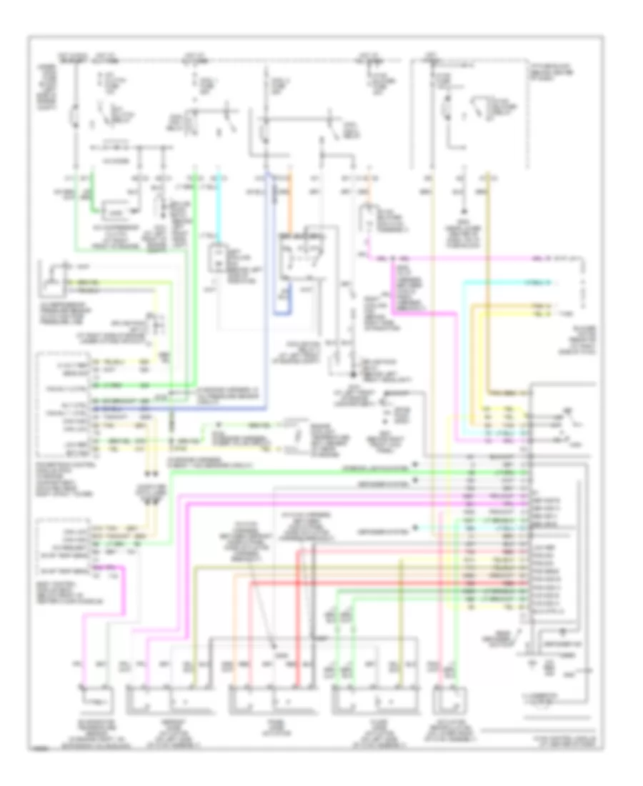
3.5L VIN 4, Compressor Wiring Diagram for Saturn Vue Red Line 2004
List of elements for 3.5L VIN 4, Compressor Wiring Diagram for Saturn Vue Red Line 2004:
- (at right side
- (in engine harness,
- A/c clutch fuse 10a
- A/c clutch relay
- A/c compressor clutch (at right front of engine)
- A/c diode
- A/c press sens
- A/c refrigerant pressure sensor (in a/c high side pressure line)
- A/c req sig
- A/c request
- A12
- A6 c1
- A6 c2
- B12
- Body control module (bcm) (below front of center floor console)
- C11
- Can high
- Can low
- Clu rly ctrl
- Computer data lines system
- E11
- Evap temp sens
- Evaporator temperature sensor (in engine compt, on expansion valve block)
- G101 (at left front of engine compt)
- Hot at all times
- Hot in run or start
- Hvac control module (at center of dash)
- In a/c pressure sensor circuit)
- Logic
- Of engine, under intake air duct)
- Powertrain control module (pcm) (in engine compt, mounted near right strut tower)
- S120
- Splice pack sp101 (behind left front headlight)
- Splice pack sp113
- Tan
- Underhood fuse block (left side of engine compt)
3.5L VIN 4, Manual A/C Wiring Diagram for Saturn Vue Red Line 2004
List of elements for 3.5L VIN 4, Manual A/C Wiring Diagram for Saturn Vue Red Line 2004:
- (in engine harness, in
- (in engine harness, in bank 1 ho2 sensors circuit)
- (in hvac harness, between c202 & panel mode actuator harness breakout)
- (in hvac harness, between defrost mode & panel mode actuator harness breakout)
- 5 volt ref
- 87a
- A/c clutch fuse 10a
- A/c clutch relay
- A/c compressor clutch (at right front of engine)
- A/c diode
- A/c pressure sensor circuit)
- A/c refrigerant pressure sensor (in a/c high side pressure line)
- A/c req sig
- A/c request
- A11
- A12
- A2 c1
- A6 c1
- A6 c2
- A7 c3
- Actuator recirculation (on lower front of hvac assembly)
- B c5
- B11 c1
- B12
- Blower motor resistor (at right side of hvac)
- Blw mtr lo
- Body control module (bcm) (below front of center floor console)
- C10
- C11
- Can high
- Can low
- Computer data lines system
- Cool 1 fuse 25a
- Cool 2 fuse 25a
- Cool fan 1 relay
- Cool fan 2 relay
- Cooling fan relay 3 (at left front of engine compt)
- Def mod a
- Def mod b
- Defogger ind
- Defogger system
- Defrost mode actuator (on left side of hvac assembly)
- E11
- Ect sig
- Engine coolant temperature (ect) sensor (at rear of engine)
- Evap temp sens
- Evaporator temperature sensor (in engine compt, on expansion valve block)
- F2 c3
- Fan rly 1 ctrl
- Fan rly 2 ctrl
- Floor mode actuator (on left side of hvac assembly)
- Flr mod a
- Flr mod b
- Front of engine compt)
- G101 (at left front of engine compartment)
- G201 (behind right front kick panel)
- G203 (near lower center of dash, on i/p fuse block)
- Gnd
- High
- Hot at all times
- Hot in run
- Hot in run or start
- Hvac blower (on hvac assembly)
- Hvac blower fuse 40a
- Hvac blower relay
- Hvac control module (at center of dash)
- Hvac fuse 10a
- I/p fuse block (behind center of dash)
- Ign
- Illumination
- Interior lights system
- Left cooling fan (behind left side of radiator)
- Logic
- Low ref
- Off
- Pan mod a
- Pan mod b
- Panel mode actuator
- Pos sens
- Pos sig
- Powertrain control module (pcm) (in engine compartment, mounted near right strut tower)
- Rear defogger switch
- Rec dr a
- Rec dr b
- Red
- Right cooling fan (behind right side of radiator)
- Rly ctrl
- S120
- S122
- S124 (in engine harness, in egr valve circuit)
- S206
- S207
- Sens sig
- Spice pack sp201
- Splice pack sp101 (behind left front headlight)
- Splice pack sp101 (behind left g101 (at left front head- light)
- Splice pack sp113 (at right side of engine, under intake air duct)
- Tan
- Under- hood fuse block (left side of engine compt)