AIR CONDITIONING
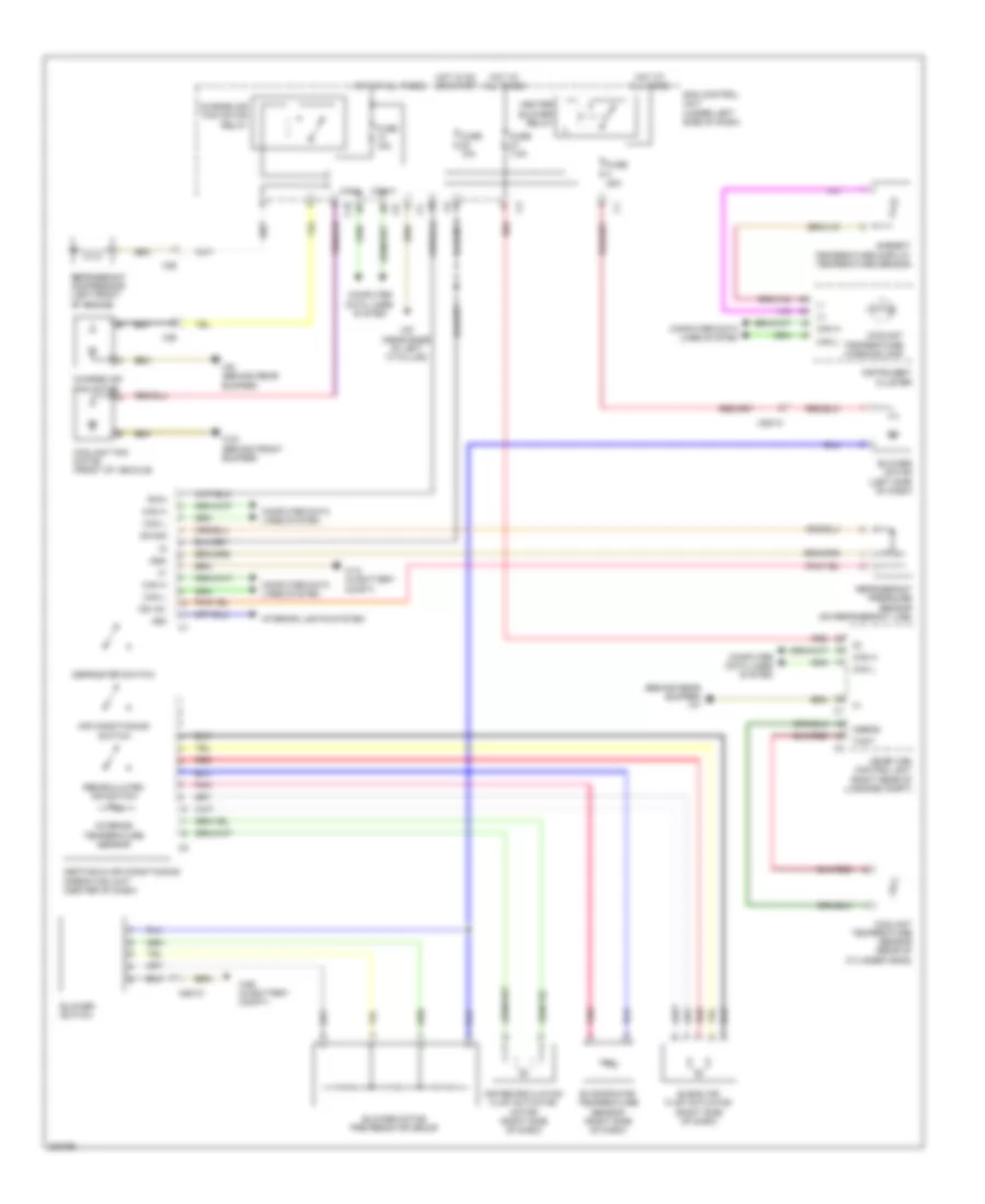
Automatic A/C Wiring Diagram for Smart Fortwo BRABUS 2010
List of elements for Automatic A/C Wiring Diagram for Smart Fortwo BRABUS 2010:
- (+)
- (-)
- (behind rear bumper) w7
- 58d
- Air conditioning switch
- Air recirculation flap actuator motor (right side of dash)
- Ambient temperature display temperature sensor
- Blend air flap actuator (right side of dash)
- Blower motor (left side of dash)
- Blower motor pre resistor group
- Blower switch
- C10
- Can h
- Can l
- Can-h
- Can-l
- Charge air fan motor
- Charge air fan motor relay
- Computer data lines system
- Coolant fan motor (front of vehicle)
- Coolant temperature sensor (rear of cylinder head)
- Coolant temperature warning lamp
- Defroster switch
- Dg +5v
- Dg sig
- Dgm
- Evaporator temperature sensor (right side of dash)
- Fuse 10a
- Fuse 15a
- Fuse 25a
- Fuse 7.5a
- Heater blower relay
- Heating & air conditioning operating unit (center of dash)
- Hot at all times
- Hot in on or start
- Instrument cluster
- Interior lights system
- Interior temperature sensor
- Me-sfi (me) control unit (right rear of luggage compt)
- Msens
- Pnk
- Recirculated air switch
- Red
- Refrigerant compressor (left front of engine)
- Refrigerant pressure sensor (on refrigerant line)
- Rwh
- Sam control unit (under left side of dash)
- Tmot
- W10 (in battery compt)
- W26 (in battery compt)
- W43 (behind front bumper)
- W6 (behind rear bumper)
- W9 (near base of left "a" pillar)
- X26
- X85/10
 English