AIR CONDITIONING
1.0L
1.0L, Automatic A/C Wiring Diagram for Smart Fortwo Passion 2014

List of elements for 1.0L, Automatic A/C Wiring Diagram for Smart Fortwo Passion 2014:
ELECTRIC
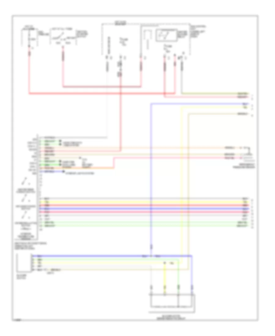
Electric, Automatic A/C Wiring Diagram (1 of 2) for Smart Fortwo Passion 2014
List of elements for Electric, Automatic A/C Wiring Diagram (1 of 2) for Smart Fortwo Passion 2014:
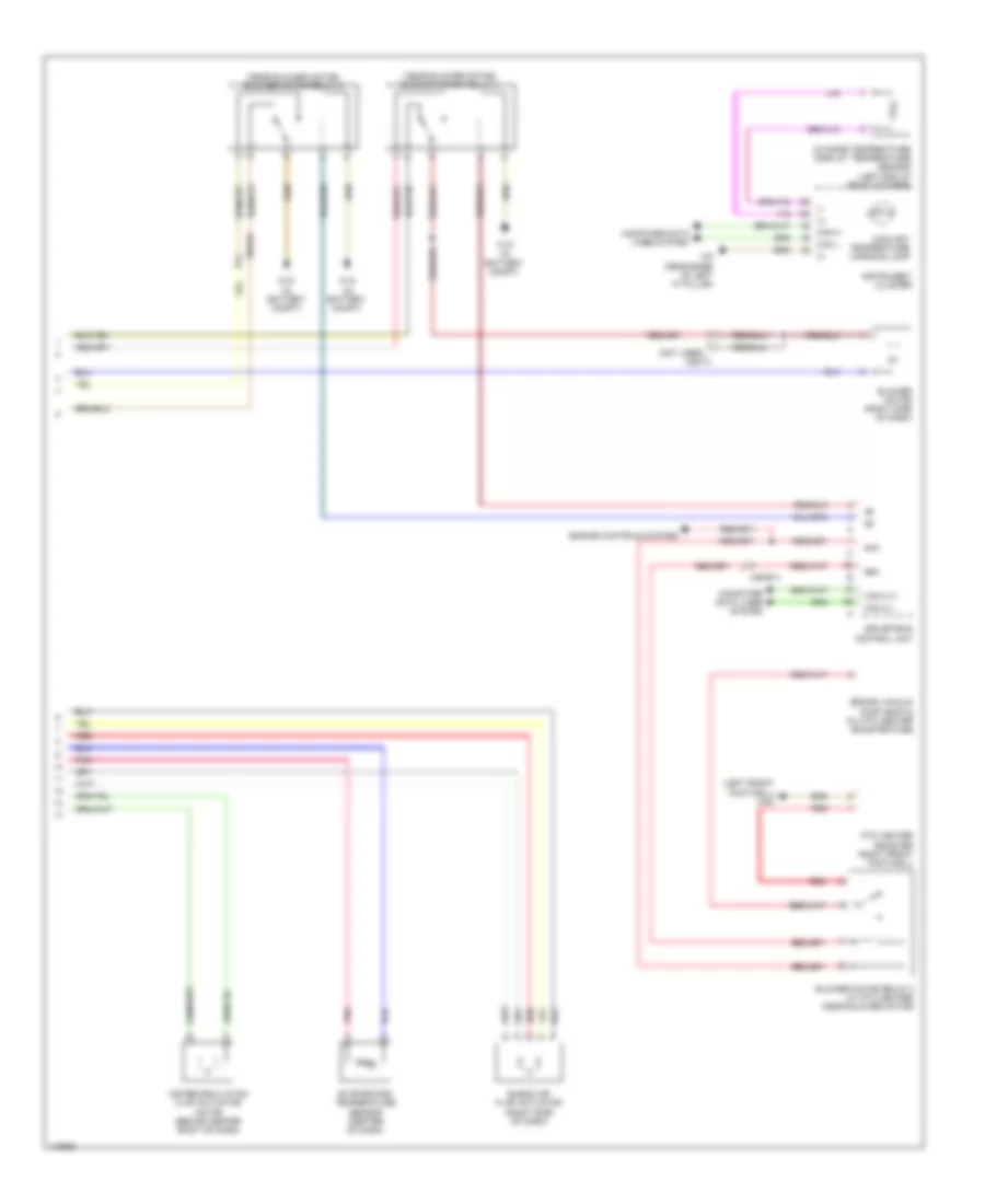
Electric, Automatic A/C Wiring Diagram (2 of 2) for Smart Fortwo Passion 2014
List of elements for Electric, Automatic A/C Wiring Diagram (2 of 2) for Smart Fortwo Passion 2014: