AIR CONDITIONING
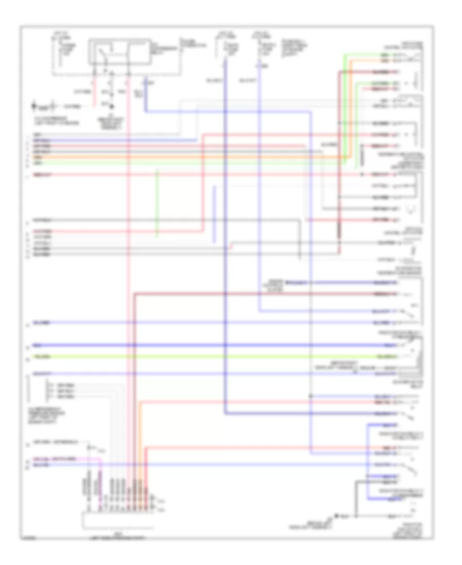
Automatic A/C Wiring Diagram (1 of 2) for Suzuki Grand Vitara Premium 2010

List of elements for Automatic A/C Wiring Diagram (1 of 2) for Suzuki Grand Vitara Premium 2010:
- (behind right side of dash) j/c g78
- 2.4l
- 3.2l
- Blower fan motor (behind right side of dash)
- Blower motor controller
- Body control module (bcm) (behind left side of dash)
- Computer data lines system
- Diode 2 (behind right side of dash)
- Dome fuse 15a
- E82
- Ect sensor (left rear of engine)
- Fr blw fuse 40a
- Fuse box 2 (left rear of engine compt)
- G03
- G16
- G30
- G32
- Hot at all times
- Hot in on
- Hot in on or start
- Hvac control module
- Ig2 sig fuse 15a
- Inside air temperature sensor
- Interior lights system
- J/c g76 (behind left side of dash)
- J/c g81 (behind left side of dash)
- Junction block (j/b) (behind left side of dash)
- Meter fuse 10a
- Pnk
- Radiator fan motor 1 (left front of engine compt)
- Red
- Sunlight sensor (under top left side of dash)
Automatic A/C Wiring Diagram (2 of 2) for Suzuki Grand Vitara Premium 2010
List of elements for Automatic A/C Wiring Diagram (2 of 2) for Suzuki Grand Vitara Premium 2010:
- (behind right headlight assembly) g7
- 2.4l
- 3.2l
- A/c compressor (left front of engine)
- A/c compressor relay
- A/c refrigerant pressure sensor (left front of engine compt)
- Air flow control actuator
- Air intake control actuator
- Blower motor relay
- C37
- Cprsr fuse 15a
- E23
- E37
- E58
- Ecm (left side of engine compt)
- Engine controls system
- Evaporator temperature sensor
- Fuse box 1 (right rear of engine compt)
- G7 (behind right headlight assembly)
- G9 (behind left headlight assembly)
- Hot at all times
- Pnk
- Power integration
- Radiator fan motor 2 (left front of engine compt)
- Radiator fan relay 1 (in relay box 1)
- Radiator fan relay 2 (in relay box 1)
- Radiator fan relay 3 (in relay box 2)
- Rdtr 2 fuse 30a
- Rdtr fuse 30a
- Red
- Temperature control actuator (under right center of dash)