AIR CONDITIONING
A/C Wiring Diagram for Suzuki Swift 1995

List of elements for A/C Wiring Diagram for Suzuki Swift 1995:
- (1995)
- (1996)
- (1996) (1995)
- 1995 vftc c
- A/c 1 relay
- A/c 2 relay
- A/c amplifier (below right side of i/p)
- A/c compressor clutch
- A/c condenser fan motor
- A/c off
- A/c relay
- A/c req
- A/c switch
- Blower motor
- Blower motor resistor (behind right side of i/p)
- Blower speed selector switch
- C21
- C23
- Dual pres sw
- Dual pressure switch (right rear of engine compartment)
- E22
- E23
- E62
- E63
- Engine control module (behind right side of i/p, near glove box)
- Engine controls system
- Evap temp
- Evaporator thermistor (behind right side of i/p)
- Fuse 21 15a
- Fuse 22 20a
- Fuse 4 30a
- Fuse 7 15a
- G03
- G100 (left front of engine compt)
- G101 (right front of engine compt)
- G20
- G200 (left kick panel)
- G206 (center of i/p)
- G24
- Ground
- Hot at all times
- Hot in on
- Hot in on or start
- Idle up
- Idle-up
- Ign
- Interior lights system
- J/b
- Main fuse box
- Off
- Pnk
- Radiator fan motor
- Rdtr fan relay
- Relay box
- Relay ctrl
- Sensor ground
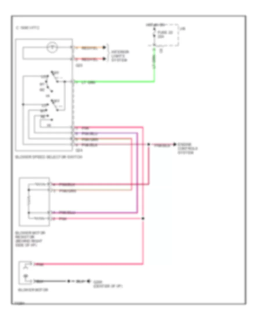
Heater Wiring Diagram for Suzuki Swift 1995
List of elements for Heater Wiring Diagram for Suzuki Swift 1995:
- 1995 vftc c
- Blower motor
- Blower motor resistor (behind right side of i/p)
- Blower speed selector switch
- Engine controls system
- Fuse 22 20a
- G20
- G206 (center of i/p)
- G24
- Hot in on
- Interior lights system
- J/b
- Off
- Pnk
 English