AIR CONDITIONING
Automatic A/C Wiring Diagram (1 of 2) for Suzuki XL-7 2003

List of elements for Automatic A/C Wiring Diagram (1 of 2) for Suzuki XL-7 2003:
- A/c compressor
- A/c compressor relay (in underhood fuse/relay box)
- A/c condenser fan high relay 1 (in underhood fuse/relay box)
- A/c condenser fan high relay 2 (in underhood fuse/relay box)
- A/c fuse 25a
- Body control module (behind center of dash)
- C51-3
- Condenser fan motor
- Condenser fan relay (in underhood fuse/relay box)
- E120
- E121
- E61
- Ecm/pcm (behind glove box)
- Ect sensor (at top left of engine)
- G10 (under right kick panel)
- G53
- G54
- G55
- G57
- G7 (behind left headlight)
- G8 (behind right headlight)
- Heater fuse 15a
- Hot at all times
- Hot in on
- Htr fuse 60a
- J/c (e45)
- Main fuse box (in underhood fuse/relay box)
- Outdoor sensor (at right front of engine compartment)
- Pnk
- Red
- Triple switch (at right front of engine compartment)
- Underdash fuse/relay box (at lower left side of dash)
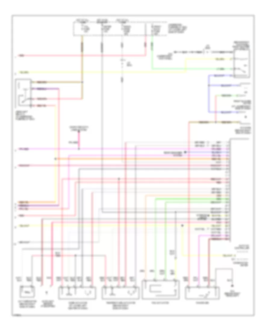
Automatic A/C Wiring Diagram (2 of 2) for Suzuki XL-7 2003
List of elements for Automatic A/C Wiring Diagram (2 of 2) for Suzuki XL-7 2003:
- (at lower left
- (at lower right side of dash)
- (behind right
- (behind right kick panel) front blower motor relay
- A/c diode (behind right end of dash)
- A/c thermistor
- Auto a/c controller
- Autolight sensor (if equipped)
- Center of dash)
- Combination meter
- Computer data lines system
- Fan actuator
- Fan driver
- Front blow fuse 40a
- Front blower motor
- G10 (under right kick panel)
- G11
- G14 (behind right headlight)
- Headlight relay 2 (in underdash fuse/relay box)
- Hot at all times
- Hot in on or start
- Interior lights system
- J/c (e44)
- J/c (e45)
- Meter fuse 10a
- Mode actuator
- Pnk
- Radio/ dome fuse 15a
- Rear degogger system
- Red
- Side of dash)
- Tail fuse 10a
- Temperature actuator
- Underdash fuse/relay box (at lower left side of dash)
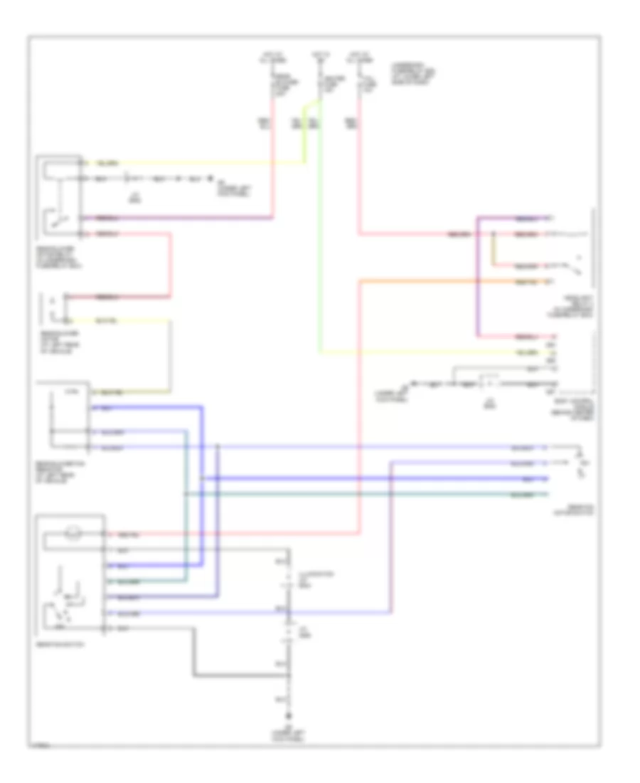
Rear A/C Wiring Diagram for Suzuki XL-7 2003
List of elements for Rear A/C Wiring Diagram for Suzuki XL-7 2003:
- Body control module (behind center of dash)
- G54
- G55
- G57
- G9 (under left kick panel)
- Headlight relay 2 (in underdash fuse/relay box)
- Heater fuse 15a
- Hot at all times
- Hot in on
- Illumination j/c (e44)
- J/c (e45)
- J/c (g29)
- Off
- Rear blower fan resistor (at left rear of vehicle)
- Rear blower fuse 20a
- Rear blower motor (at left rear of vehicle)
- Rear blower motor relay (in underdash fuse/relay box)
- Rear fan motor switch
- Rear fan switch
- Tail fuse 10a
- Underdash fuse/relay box (at lower left side of dash)