AIR CONDITIONING
Automatic A/C Wiring Diagram (1 of 2) for Suzuki XL7 Luxury 2007

List of elements for Automatic A/C Wiring Diagram (1 of 2) for Suzuki XL7 Luxury 2007:
- (in i/p harness, 10 cm from acceleration pedal position (app) sensor breakout)
- (left side of dash)
- (left side of dash) inside air temperature sensor
- (on hvac module)
- (on left side of hvac assembly)
- 5-volt ref
- Actr pos sig
- Ambient air temperature sensor (below lf headlight, on bumper bar)
- Ambient light sensor (upper left dash trim panel)
- Batt pos volt
- Body control module (bcm) (center of dash, behind hvac control module)
- Computer data lines system
- Def rly ctrl
- Defogger system
- Dimming sig
- Dr ctrl
- Drv sens
- Drv sens sig
- Evaporator temperature sensor (in engine compt, next to expansion valve block)
- G201 (behind right front kick panel)
- G203 (lower center of dash, on i/p fuse block)
- Gnd
- Hot at all times
- Hot w/ ign main relay 31 energized
- Hvac control module (at center of dash)
- Hvac/rfa fuse 15 10a
- I/p fuse block (center of dash, beneath right side of radio)
- Ign 1 volt
- Interior lights system
- Low ref
- Low spd lan
- Lower air temperature sensor (on lower right side of temperature actuator)
- Mode actr sig
- Mode actuator
- Mode dr ctrl
- Mode mtr ctrl
- Mtr ctrl
- Mtr spd ctrl
- Pass sens
- Pass sens sig
- Pnk
- Rear a/c circuit
- Recirculation actuator
- S201
- S212 (in i/p harness, 10 cm from radio breakout)
- S214 (in hvac harness, 39 cm from c216)
- Sens ctrl
- Sens sig
- Sir display fuse 25 10a
- Sply volt
- Sw sig
- Tan
- Temp ctrl
- Temp dr ctrl
- Temp sens sig
- Temperature actuator (on hvac assembly)
- Underhood fuse block (left side of engine compt)
- Upper air temperature sensor (on upper right side of temperature actuator)
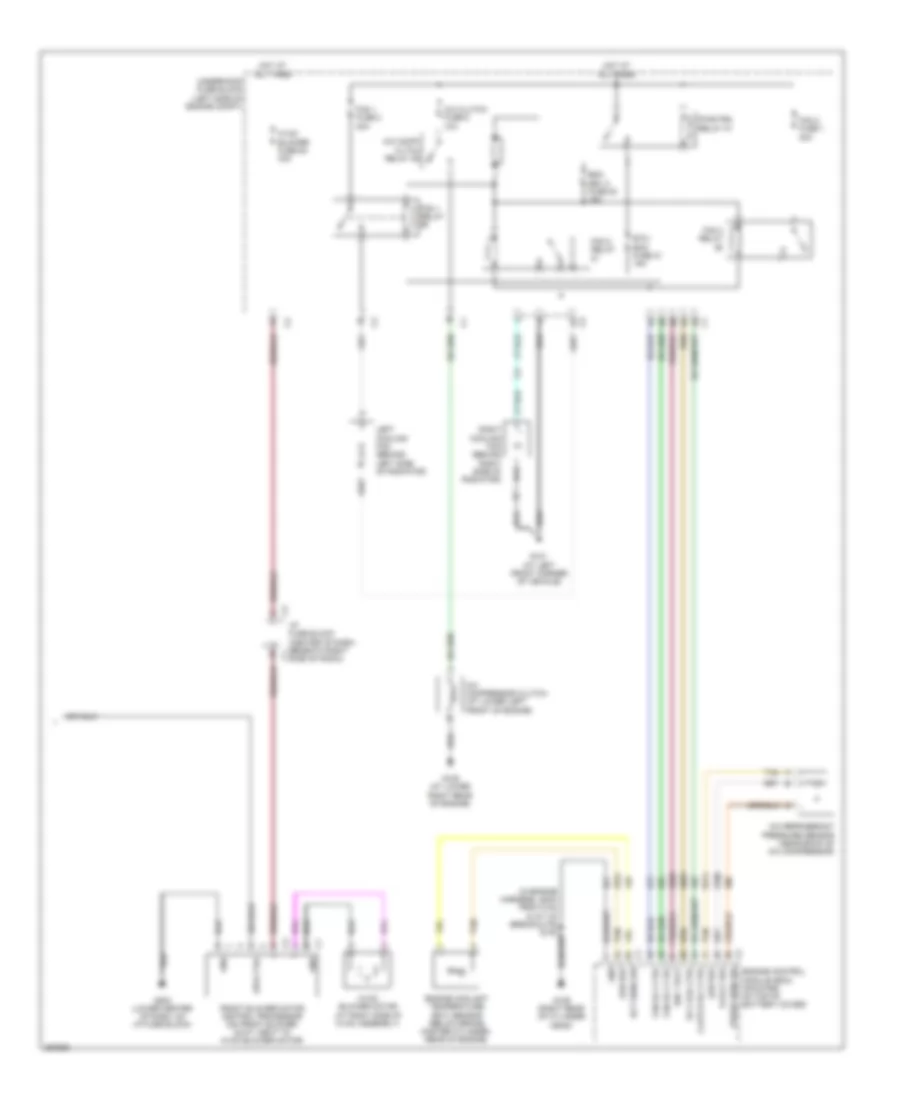
Automatic A/C Wiring Diagram (2 of 2) for Suzuki XL7 Luxury 2007
List of elements for Automatic A/C Wiring Diagram (2 of 2) for Suzuki XL7 Luxury 2007:
- (in engine harness, 28cm from c102 & a/t c2 breakouts) s100
- 5-volt ref
- A/c clutch fuse 8 10a
- A/c comp/ cltch relay 46
- A/c compressor clutch (at lower left front of engine)
- A/c refrigerant pressure sensor (near back of a/c compressor)
- Clutch rly ctrl
- Ect sens sig
- Emm dev 2 fuse 20 15a
- Engine control module (ecm) (mounted on top of battery cover)
- Engine coolant temperature (ect) sensor (below brake master cylinder, rear of engine)
- Etc/ ecm fuse 21 15a
- Fan 1 fuse 2 30a
- Fan 1 relay
- Fan 2 fuse 1 30a
- Fan 2 relay
- Fan 3 relay
- Fan rly ctrl
- Front blower motor control processor (on front blower duct, next to hvac blower motor)
- G101 (at left front corner of vehicle)
- G105 (at lower right rear of engine)
- G109 (right rear of cylinder head)
- G203 (lower center of dash, on i/p fuse block)
- Gnd
- Hot at all times
- Hvac blower fuse 54 40a
- Hvac blower motor (at right side of hvac assembly)
- I/p fuse block (center of dash, beneath right side of radio)
- Ign 1 volt
- Left cooling fan (behind left side of radiator)
- Low ref
- Press sens sig
- Pwr/trn relay 47
- Right cooling fan (behind right side of radiator)
- Rly coil ctrl
- Spd ctrl
- Tan
- Underhood fuse block (left side of engine compt)
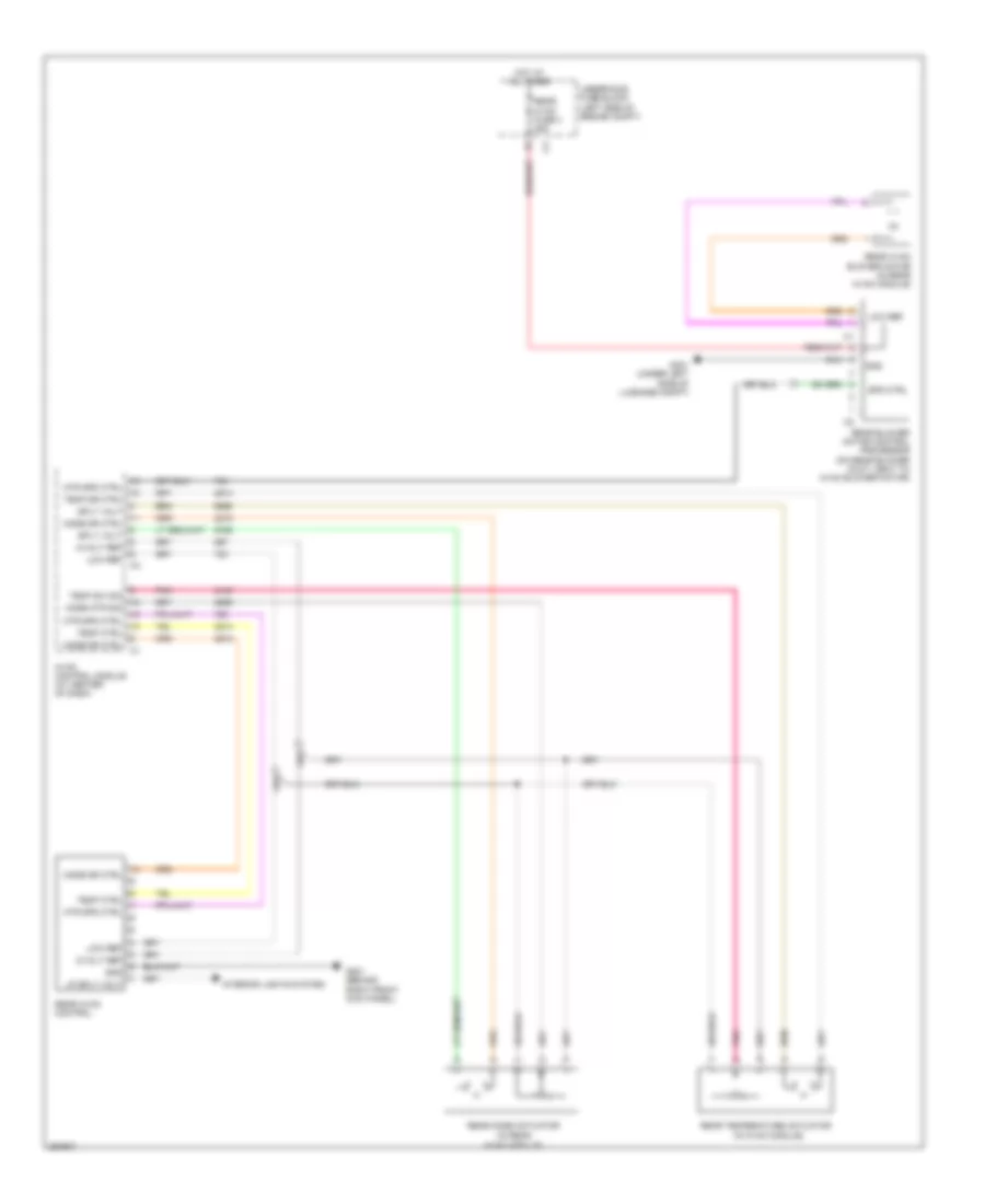
Rear A/C Wiring Diagram for Suzuki XL7 Luxury 2007
List of elements for Rear A/C Wiring Diagram for Suzuki XL7 Luxury 2007:
- (in hvac module)
- (in rear
- 5-volt ref
- G201 (behind right front kick panel)
- G401 (under left side of luggage compt)
- Gnd
- Hot at all times
- Hvac control module (at center of dash)
- Hvac module)
- Interior lights system
- Low ref
- Lp sply volt
- Mode dr ctrl
- Mode mtr sig
- Mtr spd ctrl
- Pnk
- Rear blower motor control processor (on rear blower duct, next to hvac blower motor)
- Rear hvac blower motor (in rear hvac module)
- Rear hvac control
- Rear hvac fuse 4 25a
- Rear mode actuator
- Rear temperature actuator
- Spd ctrl
- Sply volt
- Temp ctrl
- Temp dr ctrl
- Temp sw sig
- Underhood fuse block (left side of engine compt)