AIR CONDITIONING
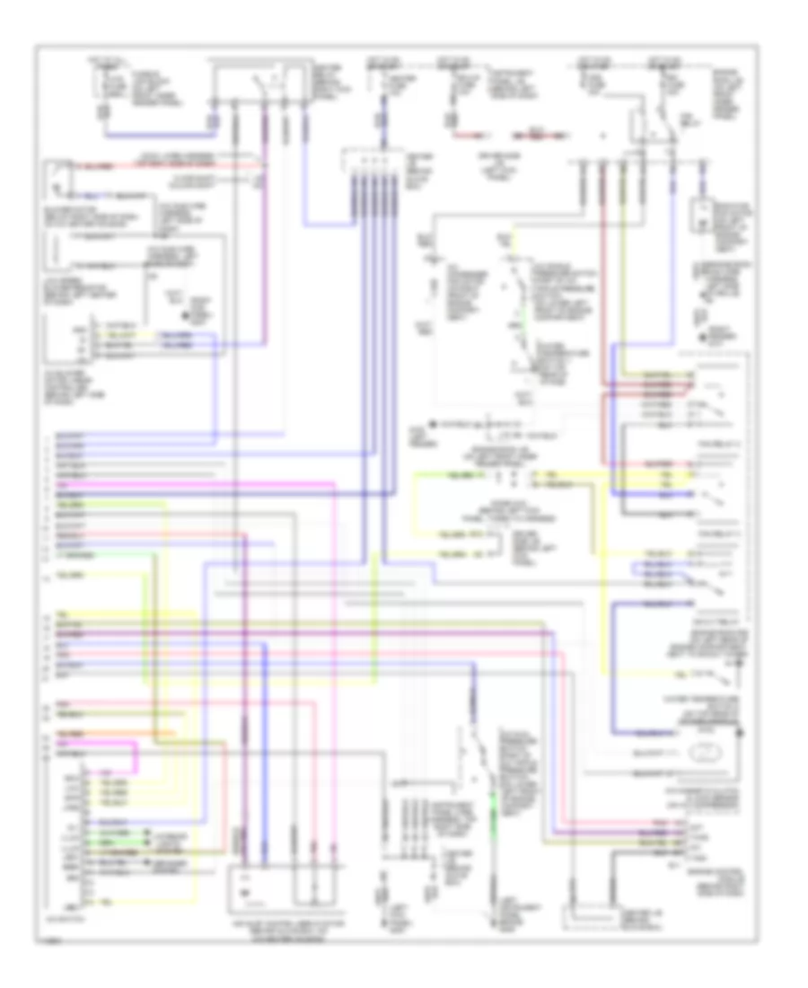
Automatic A/C Wiring Diagram (1 of 2) for Toyota Avalon XL 1999

List of elements for Automatic A/C Wiring Diagram (1 of 2) for Toyota Avalon XL 1999:
- (behind left center of dash) a/c room temperature sensor
- (behind right side of dash) a/c evaporator temperature sensor
- (left kick panel) g200
- (on lower right front of grille) a/c ambient temperature sensor
- (on top right side of dash) a/c solar sensor
- A/c amplifier (behind left center of dash)
- A10
- A11
- A12
- A13
- A14
- A15
- A16
- A17
- A18
- A19
- A20
- Ac1
- Act
- Aif
- Air
- Air mix control servo motor (behind left center of dash, on a/c-heater housing)
- Air vent mode control servo motor (behind left center of dash, on a/c-heater housing)
- Amc
- Amh
- Amout
- B/l
- B10
- B11
- B12
- B13
- B14
- B15
- B16
- B17
- B18
- Blw
- Bset
- C10
- C11
- C12
- C13
- C14
- C15
- C16
- C17
- C18
- C19
- C20
- C21
- C22
- Center j/b (behind glove box)
- Clock
- Control circuit
- Cool
- Dash)
- Def
- Ecu-b fuse 5a
- Engine room j/b (on left front inner fender panel)
- F/d
- Face
- Foot
- Gnd
- H14
- H15
- Heater control switch
- Hot at all times
- I12 (cowl wire harness, top center of dash)
- I22 (instrument panel wire harness, top right side of dash)
- I22 (instrument panel wire harness, top right side of dash)
- Ign
- Illum
- Instrument cluster system
- Interior lights system
- L-a/c
- L-auto
- L-b/l
- L-bhi
- L-blo
- L-bm1
- L-bm2
- L-def
- L-face
- L-foot
- L-frs
- L-rec
- Laut
- Lb/l
- Lbhi
- Lblo
- Lbm1
- Lbm2
- Ldef
- Led+
- Lfot
- Lockin
- Lvnt
- Maut
- Mgc
- Motor position switches
- Mset
- Off
- Pnk
- Psw
- S-a/c
- S-def
- S-mauto
- S-off
- S-r/f
- Speed
- Tam
- Tpi
- Tset
- Vent
- Ver
- Warm
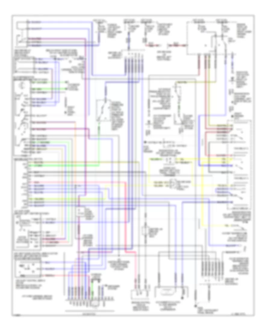
Automatic A/C Wiring Diagram (2 of 2) for Toyota Avalon XL 1999
List of elements for Automatic A/C Wiring Diagram (2 of 2) for Toyota Avalon XL 1999:
- (a/c sub wire harness, left side of dash)
- (a/c sub wire harness, left side of dash) i28
- (cowl wire harness, top rght side of dash)
- (instrument panel wire harness, top right side of dash)
- (left instrument panel brace) g206
- (left kick panel) g200
- (right fender) g101
- A/c
- A/c blower motor linear controller (behind left side of dash)
- A/c condenser fan motor (on right front of engine compart- ment)
- A/c dual pressure switch (part of a/c triple pressure switch) (on lower left front of engine compart- ment)
- A/c magnetic clutch & lock sensor (on a/c compressor)
- A/c single pressure switch (part of a/c triple pressure switch) (on lower left front of engine compartment)
- A/c switch
- Act
- Air inlet control servo motor (behind glove box, on a/c-heater housing)
- B12
- Blower motor (below right side of dash, on a/c heater housing)
- Cds fuse 30a
- Center j/b (behind glove box)
- Defogger system
- Diode (a/c) (behind left kick panel, taped to harness)
- Driver side j/b (behind left kick panel)
- Driver side j/b (left kick panel)
- E11
- Ecu-ig fuse 10a
- Engine control module (behind right side of dash)
- Engine room j/b (on left front inner fender panel)
- Engine room r/b (on left rear of engine compartment, next to shock tower)
- Fan relay
- Fan relay 2
- Fan relay 3
- Floor shift column shift
- Fusible link block (on left front inner fender panel)
- G100 (left fender)
- Gnd
- Heater fuse 10a
- Heater relay (behind right kick panel)
- Hot at all times
- Hot in on or start
- Htr fuse 50a
- I19
- I22
- I28
- Ig +
- Illum
- Instrument panel j/b (behind left side of dash)
- Interior lights system
- La/c
- Led+
- Lfrs
- Low speed blower resistor (behind left center of dash)
- Lrec
- Main wire harness, left side of grille) e4
- Mg clt relay
- Pnk
- Radiator fan motor (on left front of engine compart- ment)
- Rdef
- Rdi fuse 30a
- Sa/c
- Sf/r
- Tach
- Twho
- Water temperature switch 1 (on top rear of intake)
- Water temperature switch 2 (on top rear of intake manifold)
Manual A/C Wiring Diagram for Toyota Avalon XL 1999
List of elements for Manual A/C Wiring Diagram for Toyota Avalon XL 1999:
- (cowl wire harness, top right side of dash)
- (engine room main wire harness, left side of grille) e4
- (i/p wire harness, behind center of dash)
- (right fender) g101
- (right kick panel) g203
- 10a
- 1995 vftc c
- A/c
- A/c amplifier (behind left center of dash)
- A/c condenser fan motor (on right front of engine compartment)
- A/c dual pressure switch (part of a/c triple pressure switch) (on lower left front of engine compart- ment)
- A/c evaporator temperature sensor (behind right side of dash, on evaporator housing)
- A/c fuse (right side of dash)
- A/c magnetic clutch & lock sensor (on a/c compressor)
- A/c single pressure switch (part of a/c triple pressure switch) (on lower left front of engine compartment)
- A/c switch
- Ac1
- Act
- Air inlet control servo motor (behind glove box, on a/c-heater housing)
- Air vent mode control servo motor (behind left center of dash, on a/c-heater housing)
- B/l
- B12
- Blower resistor (behind left center of dash)
- Cds fuse 30a
- Center j/b (behind glove box)
- Control circuit
- D13
- D25
- D27
- Def
- Defogger system
- Diode (a/c) (behind left kick panel, taped to harness)
- Driver side j/b (behind left kick panel)
- Driver side j/b (left kick panel)
- E11
- Ecu-ig fuse 10a
- Engine control module (behind right side of dash)
- Engine room j/b (on left front inner fender panel)
- Engine room r/b (on left rear of engine compartment, next to shock tower)
- F/d
- Face
- Fan relay
- Fan relay 2
- Fan relay 3
- Foot
- Frs
- Fusible link block (on left front inner fender panel)
- G100 (left fender)
- G206 (left instrument panel brace)
- Gnd
- Ha/c
- Heater control switch
- Heater fuse 10a
- Heater relay (behind right kick panel)
- Hot at all times
- Hot in on
- Hot in on or start
- Htr fuse 50a
- I14
- I19 or i20
- I22 (instrument panel wire harness, top right side of dash)
- Ig+
- Ign
- Instrument panel j/b (behind left side of dash)
- Interior lights system
- L-a/c
- La/c
- Lock
- Mg clt relay
- Mgc
- Motor position switches
- Off
- Or start
- Pnk
- Radiator fan motor (on left front of engine compart- ment)
- Rdef
- Rdi fuse 30a
- Rec
- S-a/c
- Sa/c
- Sfrs
- Srec
- Tach
- Vent
- Water temp switch 1 (on top rear of intake)
- Water temperature switch 2 (on top rear of intake manifold)