AIR CONDITIONING
2.2L
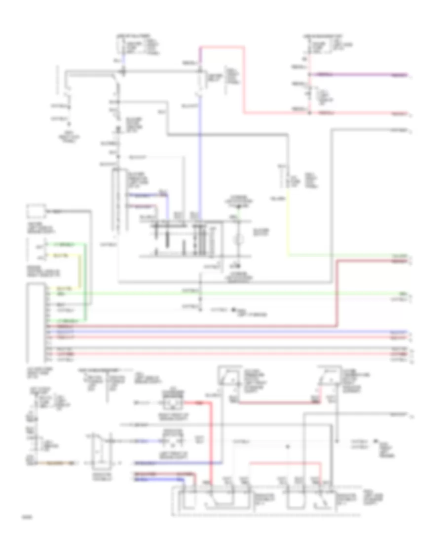
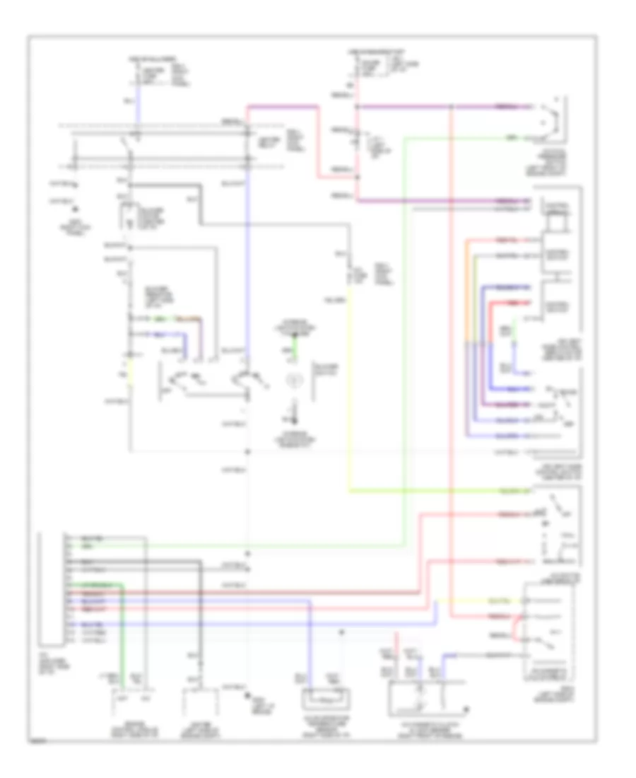
2.2L, A/C Wiring Diagram, Lever Control Type for Toyota Camry LE 1994

List of elements for 2.2L, A/C Wiring Diagram, Lever Control Type for Toyota Camry LE 1994:
- (left front of engine compt)
- (right front of engine compt)
- A/c
- A/c amplifier (right side of i/p)
- A/c condenser fan motor
- A/c dual pressure switch (left front of engine compt)
- A/c evaporator temperature sensor (right side of i/p)
- A/c fuse 10a
- A/c high pressure switch (left front of engine compt)
- A/c magnetic clutch & lock sensor (right front of engine)
- A/c magnetic clutch relay
- A/c switch (center of i/p)
- A15
- Act
- Air vent mode control servo motor (center of i/p)
- Air vent mode control switch (center of i/p)
- B/l
- Blower motor (center of i/p)
- Blower resistor (left side of i/p)
- Blower switch
- Cds fan fusible link 30a
- Control circuit
- Control switch
- Def
- Ecu-ig fuse 15a
- Engine control module (right side of i/p)
- F/d
- Face
- Foot
- G100 (front left fender)
- G202 (left i/p brace)
- G203 (right kick panel)
- Gauge fuse 10a
- Heater fuse 40a
- Heater relay
- Hot at all times
- Hot in run or start
- Igniter (left side of engine compt)
- Interior lights system (rheostat)
- Interior lights system (tail fuse)
- J/b 1 (left side of i/p)
- J/b 2 (left side of engine compt)
- J/b 3 (behind i/p)
- J/c 1 (left side of i/p)
- Off
- R/b 4 (right kick panel)
- R/b 5 (left side of engine compt)
- Radiator fan motor
- Radiator fan relay
- Radiator fan relay n0. 3
- Radiator fan relay no. 2
- Rdi fan fusible link 30a
- Red
- Water temperature switch (right radiator support)
2.2L, A/C Wiring Diagram, Push Control Type (1 of 2) for Toyota Camry LE 1994
List of elements for 2.2L, A/C Wiring Diagram, Push Control Type (1 of 2) for Toyota Camry LE 1994:
- (left front of engine compt)
- (right front of engine compt)
- A/c
- A/c amplifier (right side of i/p)
- A/c condenser fan motor
- A/c fuse 10a
- A/c high pressure switch (left front of engine compt)
- Act
- Blower motor (center of i/p)
- Blower resistor (left side of i/p)
- Blower switch
- C16
- Cds fan fusible link 30a
- Ecu-ig fuse 15a
- Engine control module (right side of i/p)
- G100 (front left fender)
- G202 (left i/p brace)
- G203 (right kick panel)
- Gauge fuse 10a
- Heater fuse 40a
- Heater relay
- Hot at all times
- Hot in run or start
- Igniter (left side of engine compt)
- Interior lights system (rheostat)
- Interior lights system (tail fuse)
- J/b 1 (left side of i/p)
- J/b 2 (left side of engine compt)
- J/b 3 (behind i/p)
- J/c 1 (left side of i/p)
- Off lo m1 m2 m3 m4 m5 hi
- R/b 4 (right kick panel)
- R/b 5 (left side of engine compt)
- Radiator fan motor
- Radiator fan relay
- Radiator fan relay n0. 2
- Radiator fan relay n0. 3
- Rdi fan fusible link 30a
- Red
- Water temperature switch (right radiator support)
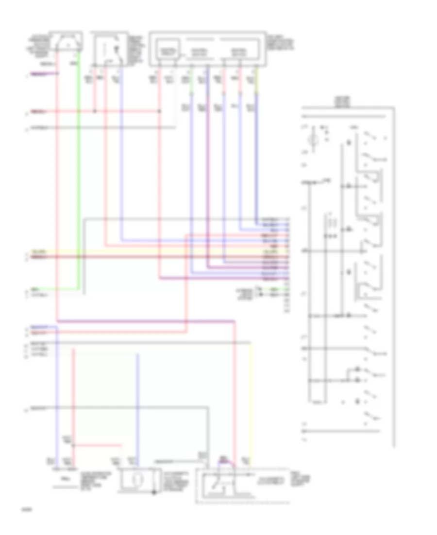
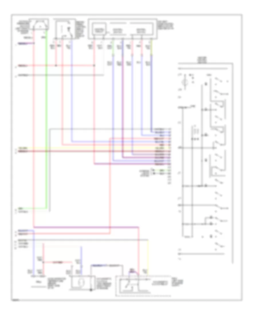
2.2L, A/C Wiring Diagram, Push Control Type (2 of 2) for Toyota Camry LE 1994
List of elements for 2.2L, A/C Wiring Diagram, Push Control Type (2 of 2) for Toyota Camry LE 1994:
- A/c dual pressure switch (left front of engine compt)
- A/c evaporator temperature sensor (right side of i/p)
- A/c magnetic clutch & lock sensor (right front of engine)
- A/c magnetic clutch relay
- Air vent mode control servo motor (center of i/p)
- Control circuit
- Control switch
- Heater control switch
- Interior lights system
- R/b 5 (left side of engine compt)
- Recirc/ fresh control servo motor (right side of i/p)
- Red
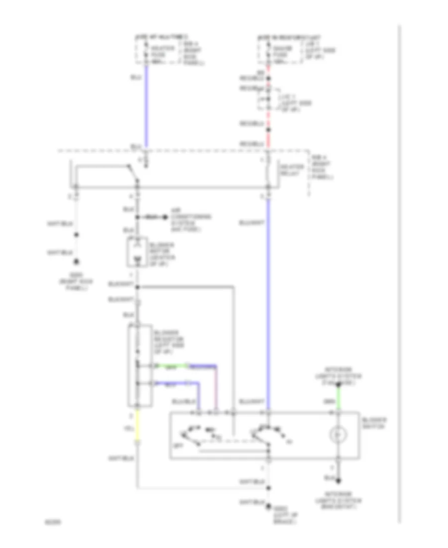
Heater Wiring Diagram, Lever Control Type for Toyota Camry LE 1994
List of elements for Heater Wiring Diagram, Lever Control Type for Toyota Camry LE 1994:
- Air conditioning system (a/c fuse)
- Blower motor (center of i/p)
- Blower resistor (left side of i/p)
- Blower switch
- G202 (left i/p brace)
- G203 (right kick panel)
- Gauge fuse 10a
- Heater fuse 40a
- Heater relay
- Hot at all times
- Hot in run or start
- Interior lights system (rheostat)
- Interior lights system (tail fuse)
- J/b 1 (left side of i/p)
- J/c 1 (left side of i/p)
- Off
- R/b 4 (right kick panel)
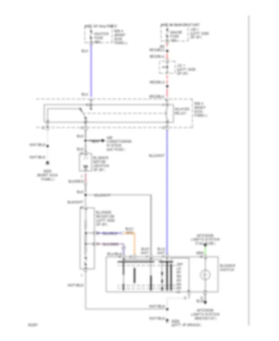
Heater Wiring Diagram, Push Control Type for Toyota Camry LE 1994
List of elements for Heater Wiring Diagram, Push Control Type for Toyota Camry LE 1994:
- Air conditioning system (a/c fuse)
- Blower motor (center of i/p)
- Blower resistor (left side of i/p)
- Blower switch
- G202 (left i/p brace)
- G203 (right kick panel)
- Gauge fuse 10a
- Heater fuse 40a
- Heater relay
- Hot at all times
- Hot in run or start
- Interior lights system (rheostat)
- Interior lights system (tail fuse)
- J/b 1 (left side of i/p)
- J/c 1 (left side of i/p)
- Off lo m1 m2 m3 m4 m5 hi
- R/b 4 (right kick panel)
3.0L
3.0L, A/C Wiring Diagram, Lever Control Type for Toyota Camry LE 1994
List of elements for 3.0L, A/C Wiring Diagram, Lever Control Type for Toyota Camry LE 1994:
- A/c
- A/c amplifier (right side of i/p)
- A/c dual pressure switch (left front of engine compt)
- A/c evaporator temperature sensor (right side of i/p)
- A/c fuse 10a
- A/c magnetic clutch & lock sensor (right front of engine)
- A/c magnetic clutch relay
- A/c switch (center of i/p)
- Act
- Air vent mode control servo motor (center of i/p)
- Air vent mode control switch (center of i/p)
- B/l
- Blower motor (center of i/p)
- Blower resistor (left side of i/p)
- Blower switch
- Control circuit
- Control switch
- Def
- Engine control module (right side of i/p)
- F/d
- Face
- Foot
- G202 (left i/p brace)
- G203 (right kick panel)
- Gauge fuse 10a
- Heater fuse 40a
- Heater relay
- Hot at all times
- Hot in run or start
- Igniter (left side of engine compt)
- Interior lights system (rheostat)
- Interior lights system (tail fuse)
- J/b 1 (left side of i/p)
- J/c 1 (left side of i/p)
- Off
- R/b 4 (right kick panel)
- R/b 5 (left side of engine compt)
- Red
3.0L, A/C Wiring Diagram, Push Control Type (1 of 2) for Toyota Camry LE 1994
List of elements for 3.0L, A/C Wiring Diagram, Push Control Type (1 of 2) for Toyota Camry LE 1994:
- A/c
- A/c amplifier (right side of i/p)
- A/c fuse 10a
- Act
- Blower motor (center of i/p)
- Blower resistor (left side of i/p)
- Blower switch
- Engine control module (right side of i/p)
- G202 (left i/p brace)
- G203 (right kick panel)
- Gauge fuse 10a
- Heater fuse 40a
- Heater relay
- Hot at all times
- Hot in run or start
- Igniter (left side of engine compt)
- Interior lights system (rheostat)
- Interior lights system (tail fuse)
- J/b 1 (left side of i/p)
- J/c 1 (left side of i/p)
- Off lo m1 m2 m3 m4 m5 hi
- R/b 4 (right kick panel)
3.0L, A/C Wiring Diagram, Push Control Type (2 of 2) for Toyota Camry LE 1994
List of elements for 3.0L, A/C Wiring Diagram, Push Control Type (2 of 2) for Toyota Camry LE 1994:
- A/c dual pressure switch (left front of engine compt)
- A/c evaporator temperature sensor (right side of i/p)
- A/c magnetic clutch & lock sensor (right front of engine)
- A/c magnetic clutch relay
- Air vent mode control servo motor (center of i/p)
- Control circuit
- Control switch
- Heater control switch
- Interior lights system
- R/b 5 (left side of engine compt)
- Recirc/ fresh control servo motor (right side of i/p)
- Red
Heater Wiring Diagram, Lever Control Type for Toyota Camry LE 1994
List of elements for Heater Wiring Diagram, Lever Control Type for Toyota Camry LE 1994:
- Air conditioning system (a/c fuse)
- Blower motor (center of i/p)
- Blower resistor (left side of i/p)
- Blower switch
- G202 (left i/p brace)
- G203 (right kick panel)
- Gauge fuse 10a
- Heater fuse 40a
- Heater relay
- Hot at all times
- Hot in run or start
- Interior lights system (rheostat)
- Interior lights system (tail fuse)
- J/b 1 (left side of i/p)
- J/c 1 (left side of i/p)
- Off
- R/b 4 (right kick panel)
Heater Wiring Diagram, Push Control Type for Toyota Camry LE 1994
List of elements for Heater Wiring Diagram, Push Control Type for Toyota Camry LE 1994:
- Air conditioning system (a/c fuse)
- Blower motor (center of i/p)
- Blower resistor (left side of i/p)
- Blower switch
- G202 (left i/p brace)
- G203 (right kick panel)
- Gauge fuse 10a
- Heater fuse 40a
- Heater relay
- Hot at all times
- Hot in run or start
- Interior lights system (rheostat)
- Interior lights system (tail fuse)
- J/b 1 (left side of i/p)
- J/c 1 (left side of i/p)
- Off lo m1 m2 m3 m4 m5 hi
- R/b 4 (right kick panel)