AIR CONDITIONING
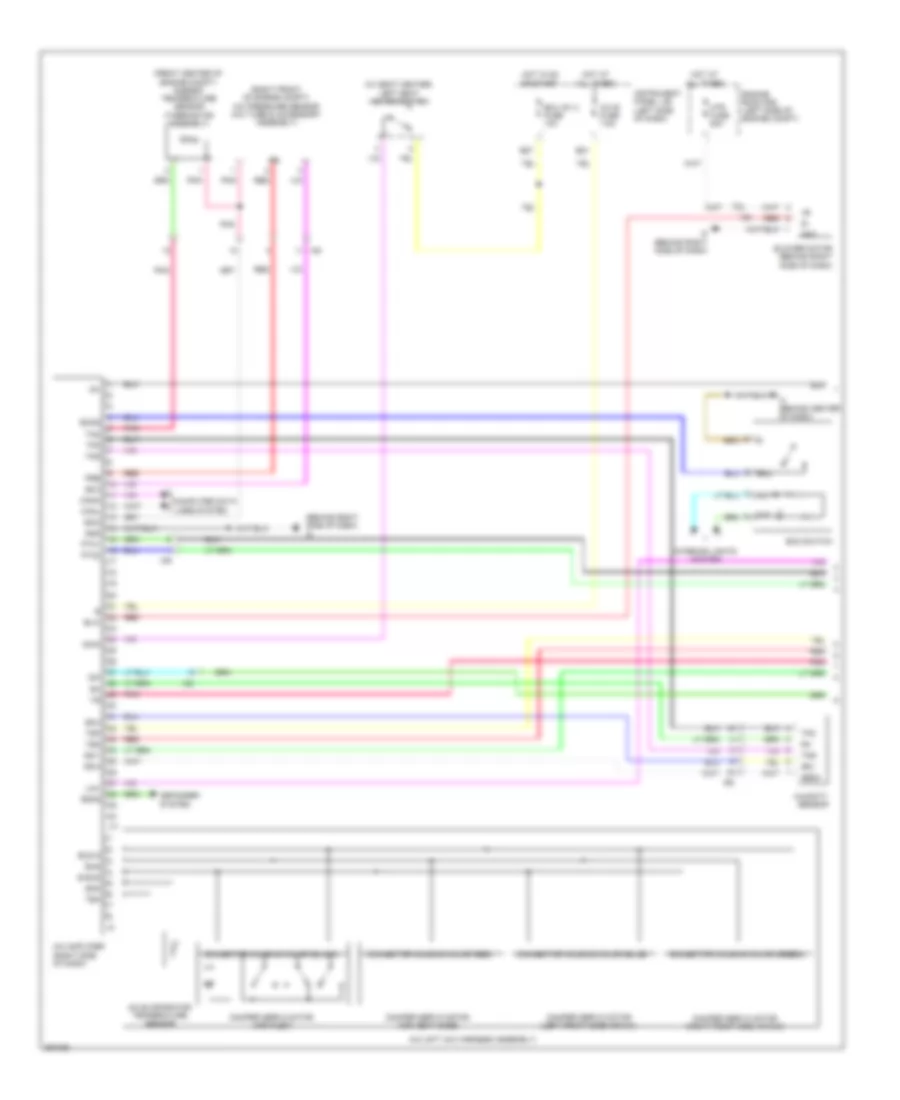
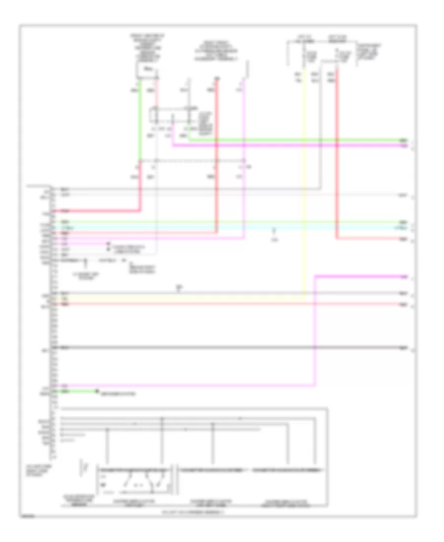
Automatic A/C Wiring Diagram, Except Hybrid (1 of 3) for Toyota Camry LE 2013

List of elements for Automatic A/C Wiring Diagram, Except Hybrid (1 of 3) for Toyota Camry LE 2013:
- (front center of engine compt) ambient temperature sensor (thermistor assembly)
- (right front of engine compt) a/c pressure sensor (a/c tube & accessory assembly)
- 3.5l
- A/c amplifier (right side of dash)
- A/c evaporator temperature sensor
- A/c unit (a/c harness assembly)
- A/c-b fuse 7.5a
- A/c-ig1 fuse 7.5a
- A70
- B bus
- B21
- B22
- B39
- Blw
- Bus
- Bus g
- Canh
- Canl
- Computer data lines system
- Connector housing color (black)
- Connector housing color (green)
- Connector housing color (red)
- Damper servo motor (air inlet)
- Damper servo motor (air vent mode)
- Damper servo motor (left front side air mix)
- Damper servo motor (right front side air mix)
- Defogger system
- E76
- Floq
- Gnd
- Hot at all times
- Hot in on or start
- I5 (behind right side of dash)
- I77
- Ia8
- Ig+
- Instrument panel j/b (left side of dash)
- J/c a70 & e76 (left side of engine compt)
- Lin1
- Lock
- Mgc
- Pnk
- Pre
- Rdfg
- Red
- S5-1
- S5-3
- Sg-1
- Sga
- Sig-2
- Sol+
- Tam
- Tea
- Tsd
- Tsp
- W/ smart key system
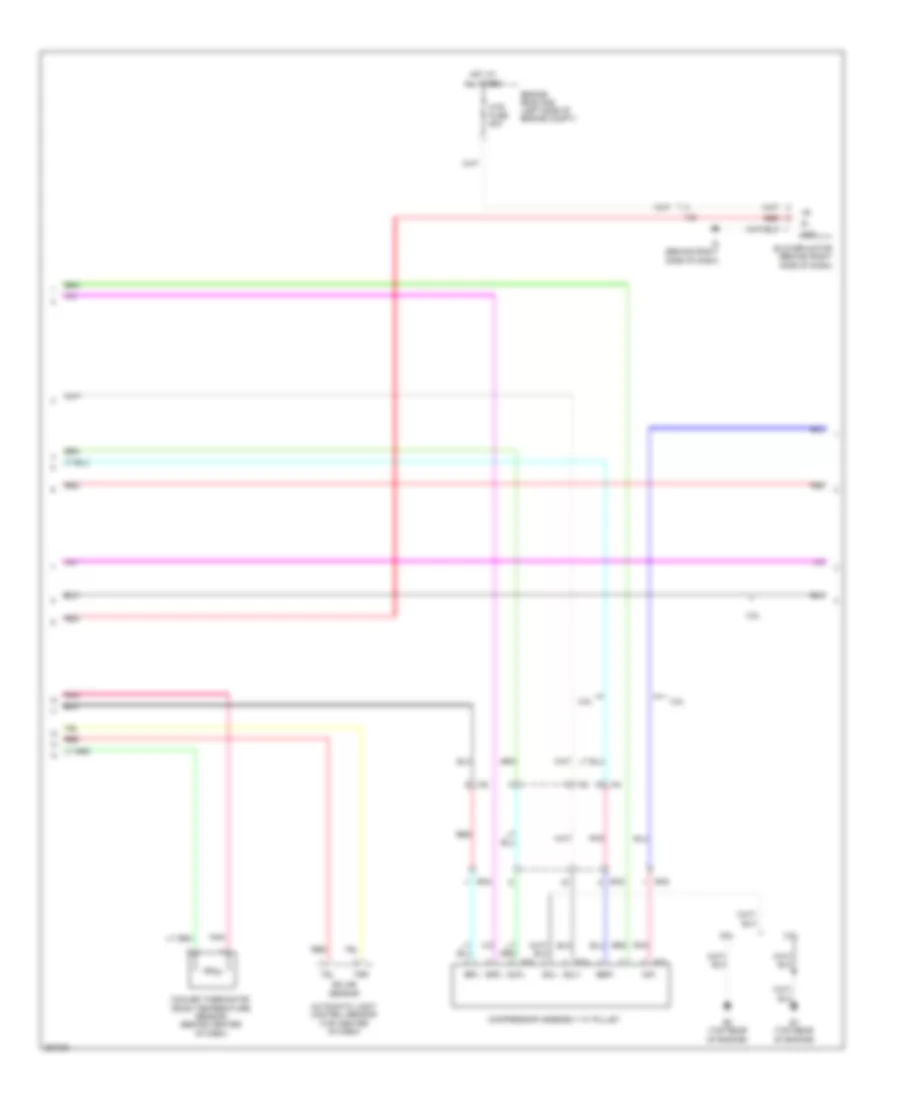
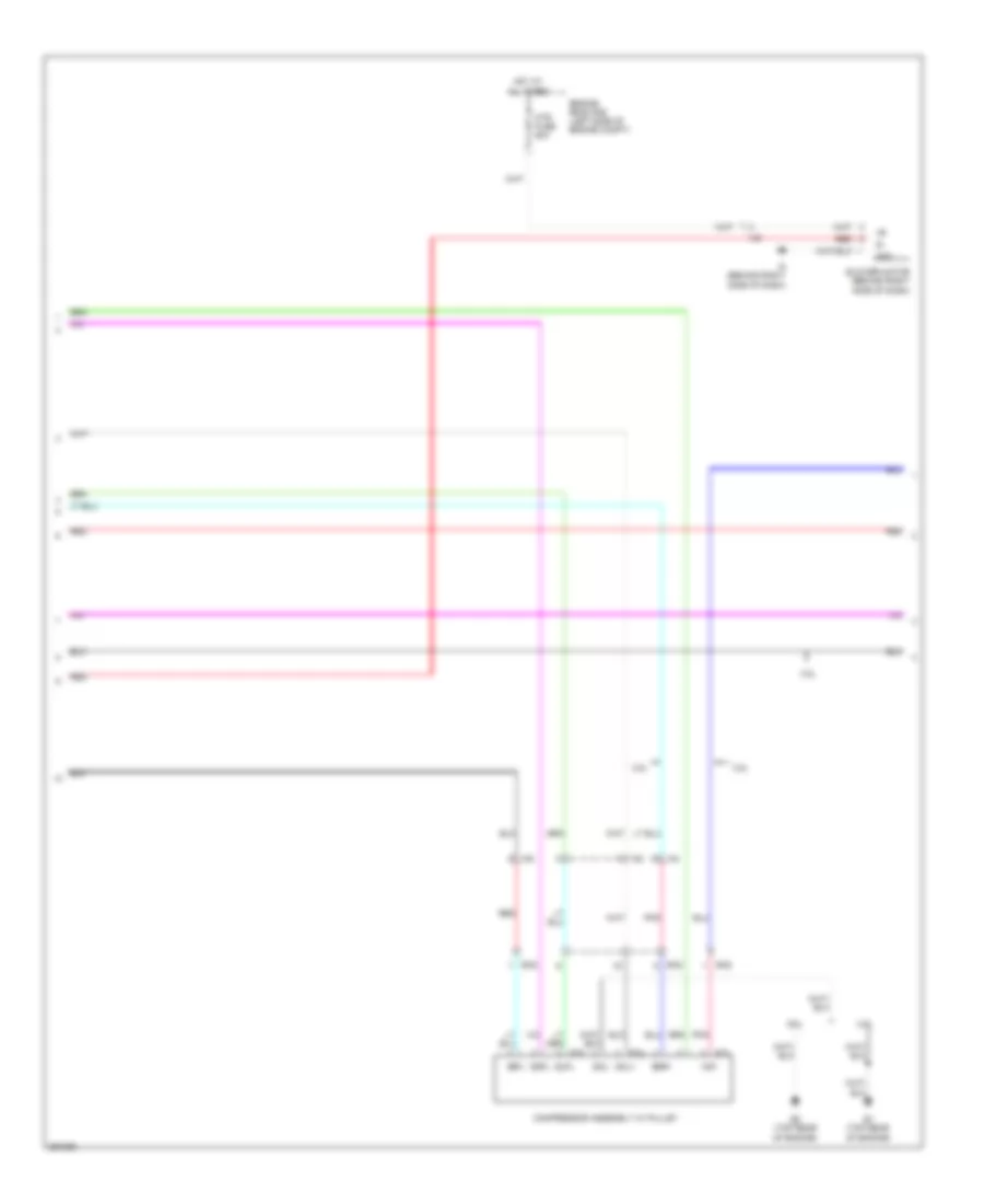
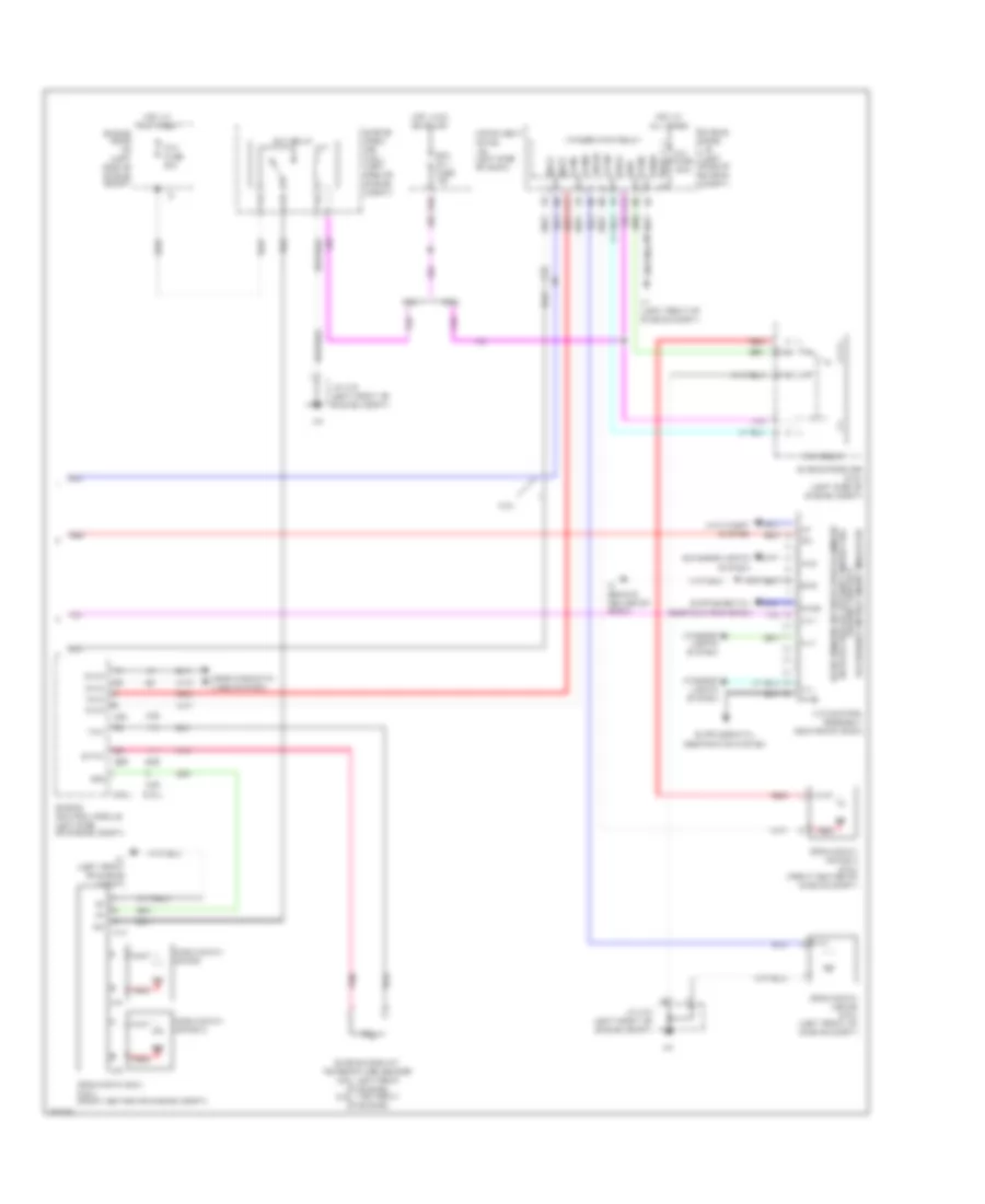
Automatic A/C Wiring Diagram, Except Hybrid (2 of 3) for Toyota Camry LE 2013
List of elements for Automatic A/C Wiring Diagram, Except Hybrid (2 of 3) for Toyota Camry LE 2013:
- 2.5l
- 3.5l
- Automatic light control sensor (top center of dash)
- Blower motor (behind right side of dash)
- Compressor assembly w/ pulley
- Cooler thermistor (room temperature sensor) (behind center of dash)
- E1 (top rear of engine)
- E2 (top rear of engine)
- E73
- E74
- E75
- Ea2
- Engine room r/b (left side of engine compt)
- Gnd
- Hot at all times
- Htr fuse 50a
- I5 (behind right side of dash)
- Ia4
- Ia6
- Ia8
- Mg+
- Pnk
- Qufl
- Red
- S5fl
- Sgfl
- Sol+
- Sol-
- Solar sensor
- Ssr+
- Tsl
- Tsr
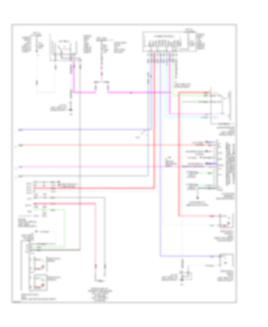
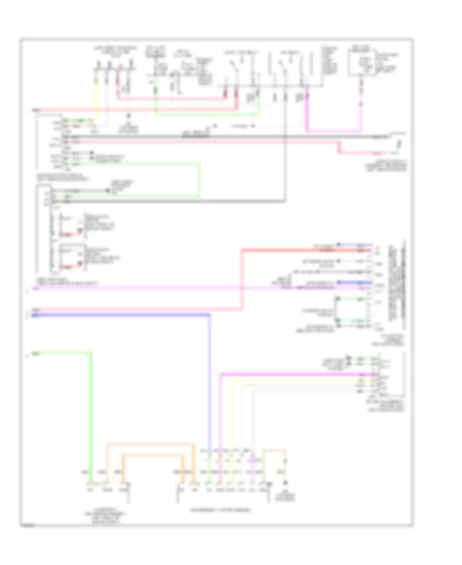
Automatic A/C Wiring Diagram, Except Hybrid (3 of 3) for Toyota Camry LE 2013
List of elements for Automatic A/C Wiring Diagram, Except Hybrid (3 of 3) for Toyota Camry LE 2013:
- (2.5l)
- (3.5l)
- +b1
- 2.5l
- 3.5l
- A/c control assembly (center of dash)
- A1 (left front of engine compt)
- A10
- A25
- Alt
- Alt fuse 120a
- Anti-theft system
- Canh
- Canl
- Cfan
- Computer data lines system
- Cooling fan ecu (3.5l) (front center of engine compt)
- Cooling fan motor
- Cooling fan motor (2.5l) (left front of engine compt)
- Cooling fan motor 2
- Cooling fan motor 2 (2.5l) (front center of engine compt)
- D36
- E26
- Ecu ig1 1 fuse 10a
- Engine control module (left side of engine compt)
- Engine coolant temperature sensor (2.5l: left rear of engine) (3.5l: top front of engine)
- Engine room j/b (left side of engine compt)
- Engine room r/b (2.5l) (left side of engine compt)
- Engine room r/b (3.5l) (left side of engine compt)
- Ethw
- Exterior lights
- F15
- F17
- Fan fuse 50a
- Fan relay
- Fan2
- Fanh
- Fanl
- Fn2s
- Gnd
- Gnd2
- Haz
- Heater switch, security indicator, rear window defogger switch, mirror
- Hot at all times
- Hot in on or start
- I3 (behind center of dash)
- Ia4
- Ig+
- Ign
- Ill+
- Ill-
- Instrument panel j/b (left side of dash)
- Integration relay
- Interior lights system
- J/c a73 (left front of engine compt)
- Lin 1
- Mcls
- Mgct
- P-ab
- Paon
- Passenger air bag on/off indicator hazard switch &
- Pnk
- Red
- Restraints system
- Rfan
- Rfc
- System
- Thw
- Z14
- Z15
Automatic A/C Wiring Diagram, Hybrid (1 of 3) for Toyota Camry LE 2013
List of elements for Automatic A/C Wiring Diagram, Hybrid (1 of 3) for Toyota Camry LE 2013:
- (behind right side of dash) i5
- (front center of engine compt) ambient temperature sensor (thermistor assembly)
- (right front of engine compt) a/c pressure sensor (a/c tube & accessory assembly)
- (w/ seat heater) left seat heater switch
- A/c amplifier (right side of dash)
- A/c b fuse 7.5a
- A/c evaporator temperature sensor
- A/c unit (a/c harness assembly)
- B bus
- B21
- B27
- Blower motor (behind right side of dash)
- Blw
- Bus
- Bus g
- Canh
- Canl
- Computer data lines system
- Connector housing color (black)
- Connector housing color (green)
- Connector housing color (red)
- Damper servo motor (air inlet)
- Damper servo motor (air vent mode)
- Damper servo motor (left front side air mix)
- Damper servo motor (right front side air mix)
- Defogger system
- Eco switch
- Ecos
- Ecu
- Ecu ig1 2 fuse 10a
- Engine room r/b (left side of engine compt)
- Gnd
- Hot at all times
- Hot in on or start
- Htr fuse 50a
- Humidity sensor
- I3 (behind center of dash)
- I5 (behind right side of dash)
- I77
- Ia6
- Ia8
- Ia9
- Idh
- Ig+
- Ill+
- Ill-
- Instrument panel j/b (left side of dash)
- Interior lights system
- Is2
- Lin1
- Pnk
- Pre
- Ptc1
- Ptc2
- Rdfg
- Red
- S5-3
- S5-4
- S5v
- Seg3
- Sg-1
- Sg-2
- Sg-4
- Sga
- Shin
- Tam
- Tea
- Tfg
- Tng
- Tsd
- Tsp
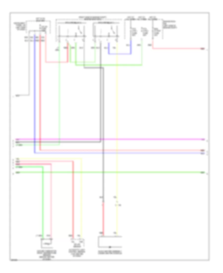
Automatic A/C Wiring Diagram, Hybrid (2 of 3) for Toyota Camry LE 2013
List of elements for Automatic A/C Wiring Diagram, Hybrid (2 of 3) for Toyota Camry LE 2013:
- (right side of engine compt) engine room r/b 2
- A/c ig1 fuse 7.5a
- Automatic light control sensor (top center of dash)
- B22
- B39
- Cooler thermistor (room temperature sensor) (behind center of dash)
- D28
- D32
- Eng w/ pmp fuse 30a
- Engine room r/b (left side of engine compt)
- Hot at all times
- Hot in on or start
- Ia6
- Instrument panel j/b (left side of dash)
- Pnk
- Ptc htr 1 fuse 50a
- Ptc htr 2 fuse 50a
- Ptc htr relay 1
- Ptc htr relay 2
- Quick heater assembly (under center console)
- Red
- Solar sensor
- Tsl
- Tsr
Automatic A/C Wiring Diagram, Hybrid (3 of 3) for Toyota Camry LE 2013
List of elements for Automatic A/C Wiring Diagram, Hybrid (3 of 3) for Toyota Camry LE 2013:
- (left front of engine compt) a5
- (left front of engine) engine water pump
- +b1
- A/c control assembly (center of dash)
- A10
- A13
- A25
- A38
- A5 (left front of engine compt)
- Acpb
- Acpe
- Anti-theft system
- Ca1h
- Ca1l
- Canh
- Canl
- Clk
- Compressor w/ motor assembly
- Computer data lines system
- Cooling fan ecu (front center of engine compt)
- Cooling fan motor (left front of engine compt)
- Cooling fan motor 2 (front center of engine compt)
- D36
- Din
- Dout
- E28
- E3 (top rear of engine)
- E65
- Ea1
- Ea2
- Ecu ig1 1 fuse 10a
- Efi 3 fuse 7.5a
- Eng w/ pmp relay
- Engine control module (left side of engine compt)
- Engine coolant temperature sensor (left rear of engine)
- Engine room j/b (left side of engine compt)
- Engine room r/b (left side of engine compt)
- Ethw
- Eti
- Exterior lights
- Fan fuse 50a
- Fan relay
- Gnd
- Haz
- Heater switch, security indicator, rear window defogger switch, mirror
- Hot at all times
- Hot in on or start
- Hot w/ efi main relay energized
- I3 (behind center of dash)
- Idh
- Ig+
- Ig1
- Ill+
- Ill-
- Instrument panel j/b (left side of dash)
- Interior lights system
- Inverter w/ converter assembly (left front of engine compt)
- Ite
- Lin 1
- Nwp
- P-ab
- Paon
- Passenger air bag on/off indicator hazard switch &
- Pgnd
- Pnk
- Power management control ecu (left side of dash)
- Red
- Restraints system
- Rfc
- Stb
- Stbi
- Swp
- System
- Thw
- Wpi
- Wpo
- Z14
- Z15
Manual A/C Wiring Diagram (1 of 3) for Toyota Camry LE 2013
List of elements for Manual A/C Wiring Diagram (1 of 3) for Toyota Camry LE 2013:
- (front center of engine compt) ambient temperature sensor (thermistor assembly)
- (right front of engine compt) a/c pressure sensor (a/c tube & accessory assembly)
- 3.5l
- A/c amplifier (right side of dash)
- A/c b fuse 7.5a
- A/c evaporator temperature sensor
- A/c ig1 fuse 7.5a
- A/c unit (a/c harness assembly)
- A70
- B bus
- B21
- B22
- B39
- Blw
- Bus
- Bus g
- Canh
- Canl
- Computer data lines system
- Connector housing color (black)
- Connector housing color (green)
- Connector housing color (red)
- Damper servo motor (air inlet)
- Damper servo motor (air vent mode)
- Damper servo motor (right front side air mix)
- Defogger system
- E76
- Floq
- Gnd
- Hot at all times
- Hot in on or start
- I5 (behind right side of dash)
- I77
- Ia8
- Ig+
- Instrument panel j/b (left side of dash)
- J/c a70 & e76 (left side of engine compt)
- Lin1
- Lock
- Mgc
- Pnk
- Pre
- Rdfg
- Red
- S5-1
- S5-3
- Sga
- Sig-2
- Sol+
- Tam
- Tea
- W/ smart key system
Manual A/C Wiring Diagram (2 of 3) for Toyota Camry LE 2013
List of elements for Manual A/C Wiring Diagram (2 of 3) for Toyota Camry LE 2013:
- 2.5l
- 3.5l
- Blower motor (behind right side of dash)
- Compressor assembly w/ pulley
- E1 (top rear of engine)
- E2 (top rear of engine)
- E73
- E74
- E75
- Ea2
- Engine room r/b (left side of engine compt)
- Gnd
- Hot at all times
- Htr fuse 50a
- I5 (behind right side of dash)
- Ia4
- Ia6
- Ia8
- Mg+
- Pnk
- Qufl
- Red
- S5fl
- Sgfl
- Sol+
- Sol-
- Ssr+
Manual A/C Wiring Diagram (3 of 3) for Toyota Camry LE 2013
List of elements for Manual A/C Wiring Diagram (3 of 3) for Toyota Camry LE 2013:
- (2.5l)
- (3.5l)
- +b1
- 2.5l
- 3.5l
- A/c control assembly (center of dash)
- A1 (left front of engine compt)
- A10
- A25
- Alt
- Alt fuse 120a
- Anti-theft system
- Canh
- Canl
- Cfan
- Computer data lines system
- Cooling fan ecu (3.5l) (front center of engine compt)
- Cooling fan motor
- Cooling fan motor (2.5l) (left front of engine compt)
- Cooling fan motor 2
- Cooling fan motor 2 (2.5l) (front center of engine compt)
- D36
- E26
- Ecu ig1 1 fuse 10a
- Engine control module (left side of engine compt)
- Engine coolant temperature sensor (2.5l: left rear of engine) (3.5l: top front of engine)
- Engine room j/b (left side of engine compt)
- Engine room r/b (2.5l) (left side of engine compt)
- Engine room r/b (3.5l) (left side of engine compt)
- Ethw
- Exterior lights
- F15
- F17
- Fan fuse 50a
- Fan relay
- Fan2
- Fanh
- Fanl
- Fn2s
- Gnd
- Gnd2
- Haz
- Heater switch, security indicatior, rear window defoger switch, mirror
- Hot at all times
- Hot in on or start
- I3 (behind center of dash)
- Ia4
- Ig+
- Ign
- Ill+
- Ill-
- Instrument panel j/b (left side of dash)
- Integration relay
- Interior lights system
- J/c a73 (left front of engine compt)
- Lin 1
- Mcls
- Mgct
- P-ab
- Paon
- Passenger air bag on/off indicator hazard switch &
- Pnk
- Red
- Restraints system
- Rfan
- Rfc
- System
- Thw
- Z14
- Z15