AIR CONDITIONING
2.2L
2.2L, Manual A/C Wiring Diagram (1 of 2) for Toyota Camry Solara SE 1999

List of elements for 2.2L, Manual A/C Wiring Diagram (1 of 2) for Toyota Camry Solara SE 1999:
- (cowl wire harness, above glove box) i5
- A/c evaporator temperature sensor (behind right side of dash, on evaporator)
- A/c switch
- A10
- A13
- A15
- A19
- A20
- A21
- Air vent mode control servo motor (behind right center of dash, on blower housing)
- B/l
- B10
- B11
- Blower motor (behind right side of dash)
- Blower resistor (behind right center of dash, on blower housing)
- Blower switch
- C18
- C19
- Control circuit
- Def
- Ecu-ig fuse 15a
- Engine control module (behind right side of dash)
- Engine room j/b 2 (on left side of engine compart- ment)
- F/d
- Face
- Foot
- Fusible link block (on left side of engine compartment)
- Gnd
- Heater control switch
- Heater fuse 10a
- Hot at all times
- Hot in on or start
- Htr fuse 50a
- Illumi- nation
- Instrument panel j/b (behind dash, left of steering column)
- Interior lights system
- J/c 11 (below top center of dash)
- J/c 29 (behind right side of dash)
- Lock
- Lock in
- Mgc
- Motor position switches
- Off
- Prs
- Thr
- W/ engine immobilizer
- W/o engine immobilizer
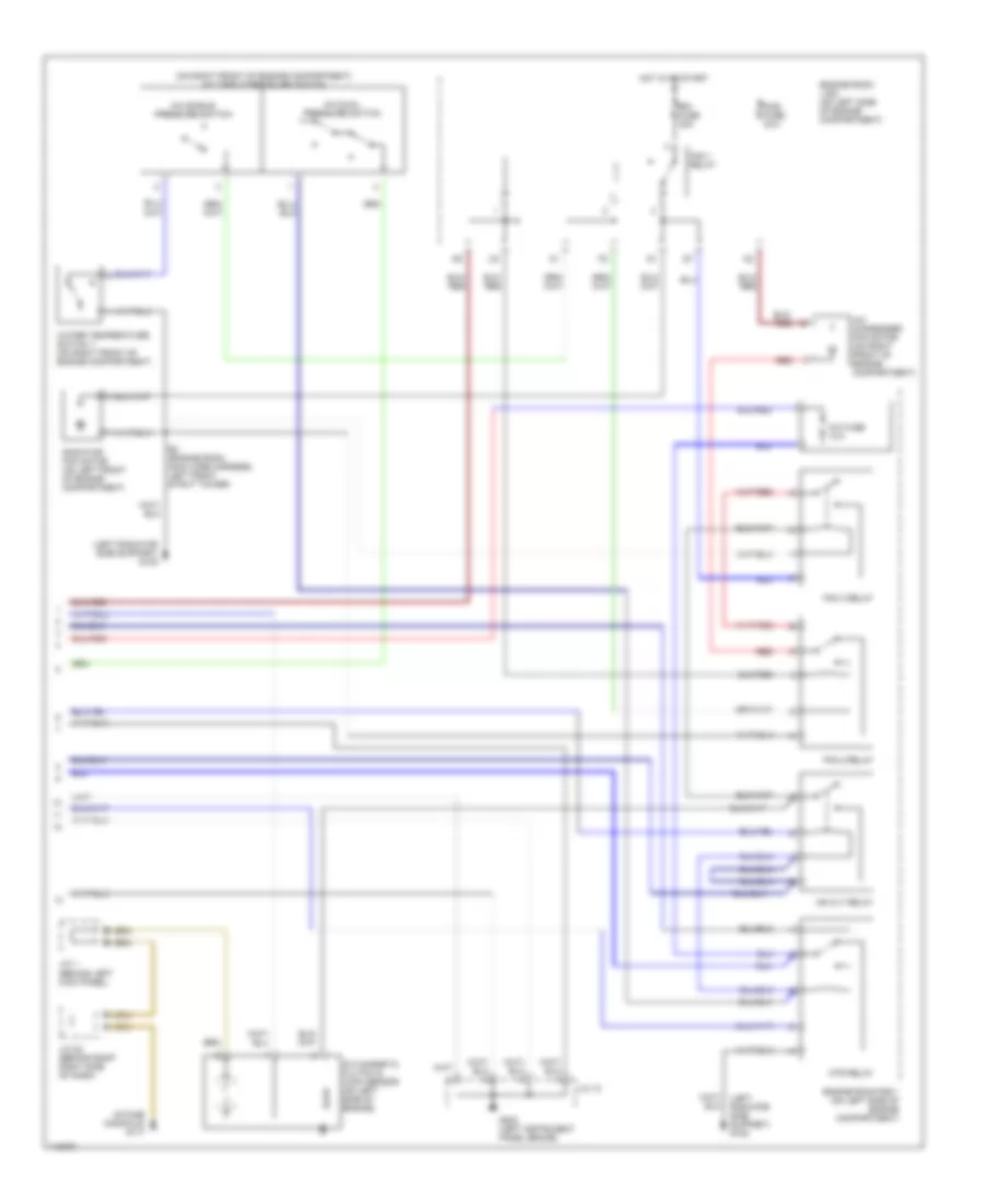
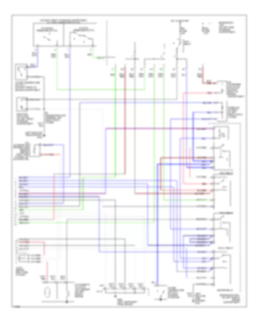
2.2L, Manual A/C Wiring Diagram (2 of 2) for Toyota Camry Solara SE 1999
List of elements for 2.2L, Manual A/C Wiring Diagram (2 of 2) for Toyota Camry Solara SE 1999:
- (intake manifold) g117
- (left radiator side support) g108
- (on right front of engine compartment) a/c triple pressure switch
- A/c condenser fan motor (on right front of engine compartment)
- A/c dual pressure switch
- A/c fuse 10a
- A/c magnetic clutch & lock sensor (on left side of engine)
- A/c single pressure switch
- Cds fuse 30a
- E4 (engine room main wire harness, left front strut tower)
- Engine room j/b 2 (on left side of engine compartment)
- Engine room r/b 1 (on left side of engine compartment)
- Fan 1 relay
- Fan 2 relay
- Fan 3 relay
- G202 (left instrument panel brace)
- Hot in or start
- Htr relay
- J/c 1 (behind left kick panel)
- J/c 10
- J/c 22 (behind right right side of dash)
- Mg clt relay
- Radiator fan motor (on left front of engine compartment)
- Rdi fuse 30a
- Red
- Water temperature switch 1 (on right front of engine compartment)
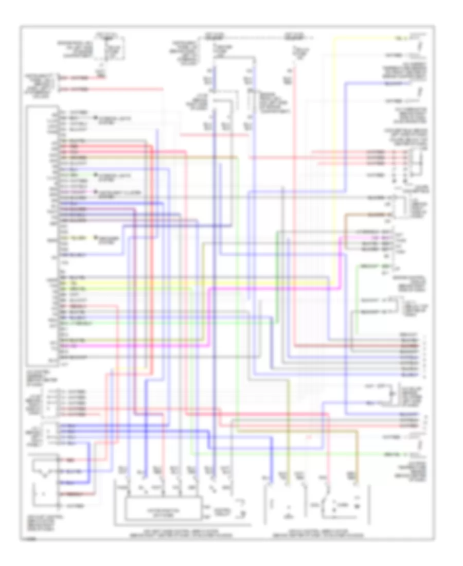
Automatic A/C Wiring Diagram (1 of 2) for Toyota Camry Solara SE 1999
List of elements for Automatic A/C Wiring Diagram (1 of 2) for Toyota Camry Solara SE 1999:
- (convertible: behind left side of dash)
- (coupe: below top center of dash)
- A/c
- A/c ambient temperature sensor (on front center of engine compartment)
- A/c control assembly (behind center of dash)
- A/c room temperature sensor (behind center of dash)
- A/c solar sensor (on upper left side of dash)
- A/c thermistor (behind right side of dash, on evaporator)
- A10
- A11
- A12
- A13
- A14
- A15
- A16
- A17
- A18
- A19
- A20
- A21
- A22
- A23
- A24
- A25
- A26
- Ac1
- Act
- Aif
- Air
- Air inlet control servo motor (behind right side of dash)
- Air mix control servo motor (behind center of dash, on blower housing)
- Air vent mode control servo motor (behind right center of dash, on blower housing)
- Amc
- Amh
- B/l
- B10
- B11
- B12
- B13
- B14
- B15
- B16
- B25
- B27
- Blw
- Control circuit
- Convertible
- Cool
- Coupe
- Def
- Defogger system
- E11
- E29
- Ecu-b fuse 10a
- Ecu-ig fuse 15a
- Engine control module (behind right side of dash)
- Engine room j/b 2 (on left side of engine compartment)
- F/d
- Face
- Foot
- Gnd
- Heater fuse 10a
- Hot at all times
- Hot in on or start
- Ig+
- Ign
- Illum
- Instrument cluster system
- Instrument panel j/b (behind dash, left of steering column)
- Interior lights system
- J/c
- J/c (behind right side of dash)
- J/c 1 (behind left kick panel)
- J/c 11 (below top center of dash)
- J/c 26 (behind right side of dash)
- J/c 29 (behind right side of dash)
- J24
- J25
- Lock
- Mgcr
- Motor position switches
- Pnk
- Psw
- Rdfg
- Red
- Spd
- Tach
- Tam
- Thwo
- Tpi
- V10
- Warm
Automatic A/C Wiring Diagram (2 of 2) for Toyota Camry Solara SE 1999
List of elements for Automatic A/C Wiring Diagram (2 of 2) for Toyota Camry Solara SE 1999:
- (cowl wire harness, above glove box) i5
- (cowl wire harness, behind top center of dash) i4
- (left radiator side support) g108
- (on right front of engine compartment) a/c triple pressure switch
- (right kick panel) g203
- A/c blower motor linear controller (behind center of dash)
- A/c condenser fan motor (on right front of engine compartment)
- A/c dual pressure switch
- A/c magnetic clutch & lock sensor (on left side of engine)
- A/c single pressure switch
- Blower motor (behind right side of dash)
- Blower resistor (behind right center of dash, on blower housing)
- Cds fuse 30a
- Diode (a/c) (in front of left front strut tower)
- E4 (engine room main wire harness, left front strut tower)
- Engine room j/b 2 (on left side of engine compartment)
- Engine room r/b 1 (on left side of engine compartment)
- Fan 1 relay
- Fan 2 relay
- Fan 3 relay
- Fusible link block (w/traction control) (on left side of engine compartment) (w/o traction control) (on right front of engine compartment)
- G202 (left instrument panel brace)
- Gnd
- Hot at all times
- Hot in or start
- Htr fuse 50a
- Htr relay
- Instrument panel j/b (behind dash, left of steering column)
- J/c (behind left side of dash)
- J/c 10
- J13
- Mg clt relay
- Radiator fan motor (on left front of engine compartment)
- Rdi fuse 30a
- Red
- Water temperature switch 1 (on right front of engine compartment)
- Water temperature switch 2 (on rear of engine)
3.0L
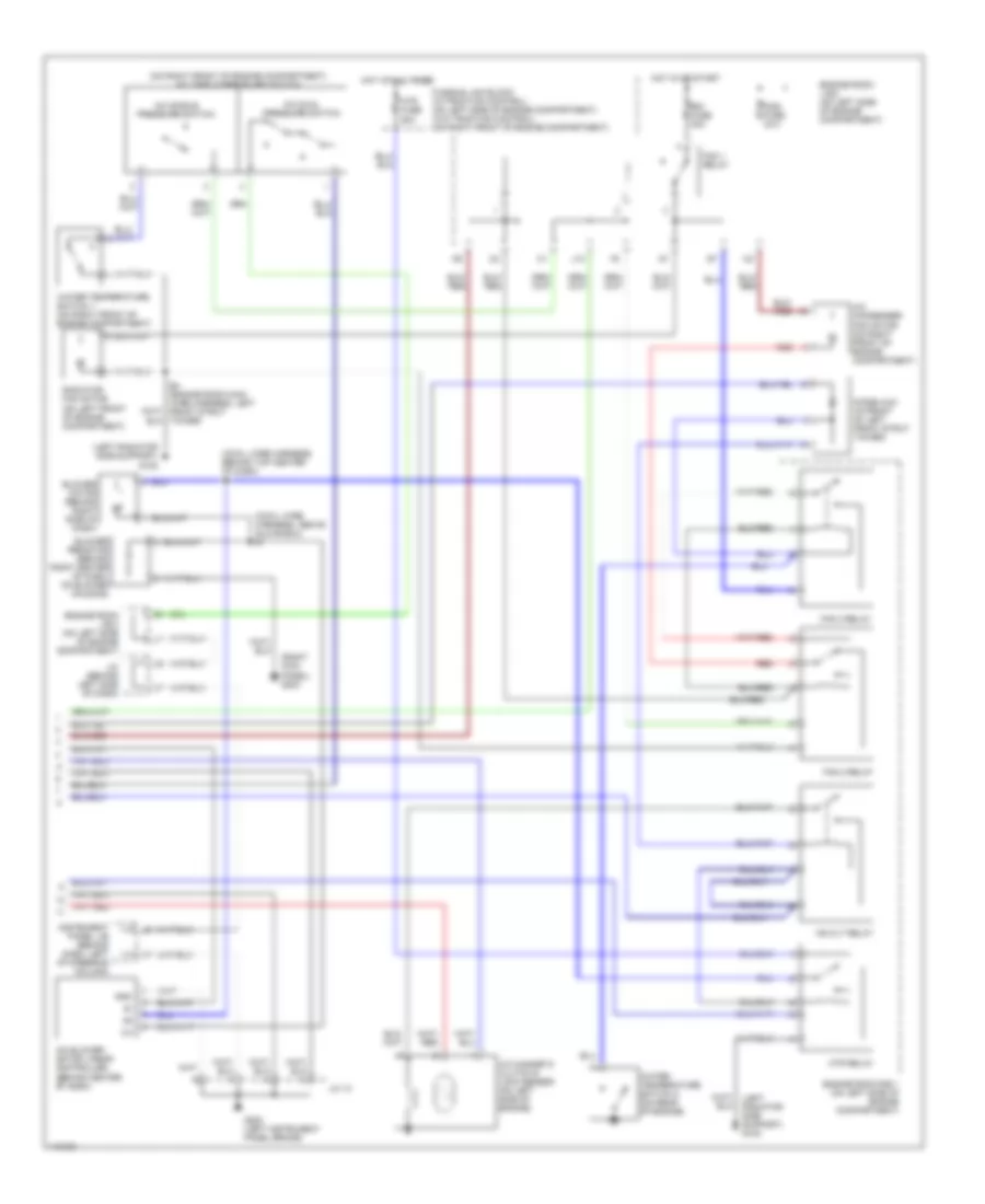
3.0L, Manual A/C Wiring Diagram (1 of 2) for Toyota Camry Solara SE 1999
List of elements for 3.0L, Manual A/C Wiring Diagram (1 of 2) for Toyota Camry Solara SE 1999:
- (cowl wire harness, above glove box) i5
- A/c
- A/c amplifier (behind glove box)
- A/c switch
- Ac1
- Act
- Air vent mode control servo motor (behind right center of dash, on blower housing)
- B/l
- B13
- B25
- B27
- Blower motor (behind right side of dash)
- Blower resistor (behind right center of dash, on blower housing)
- Blower switch
- Control circuit
- Def
- E11
- E29
- Ecu-ig fuse 15a
- Engine control module (behind right side of dash)
- Engine room j/b 2 (on left side of engine compart- ment)
- F/d
- Face
- Foot
- Fusible link block (w/traction control) (on left side of engine compartment) (w/o traction control) (on right front of engine compartment)
- Gnd
- Heater control switch
- Heater fuse 10a
- Hot at all times
- Hot in on or start
- Htr fuse 50a
- Ign
- Illumi- nation
- Instrument panel j/b (behind dash, left of steering column)
- Interior lights system
- J/c (behind right side of dash)
- J/c 11 (below top center of dash)
- J/c 29 (behind right side of dash)
- J24
- J25
- L-a/c
- Lock
- Mgc
- Motor position switches
- Off
- S-a/c
- Tach
3.0L, Manual A/C Wiring Diagram (2 of 2) for Toyota Camry Solara SE 1999
List of elements for 3.0L, Manual A/C Wiring Diagram (2 of 2) for Toyota Camry Solara SE 1999:
- (left radiator side support) g108
- (on right front of engine compartment) a/c triple pressure switch
- A/c 10a
- A/c condenser fan motor (on right front of engine compartment)
- A/c dual pressure switch
- A/c evaporator temperature sensor (behind right side of dash, on evaporator)
- A/c magnetic clutch & lock sensor (on left side of engine)
- A/c single pressure switch
- Cds fuse 30a
- Diode (a/c) (in front of left front strut tower)
- Engine room j/b 2 (on left side of engine compartment)
- Engine room r/b 1 (on left side of engine compartment)
- Fan 1 relay
- Fan 2 relay
- Fan 3 relay
- G202 (left instrument panel brace)
- Heater relay
- Hot in or start
- J/c 10
- J/c 26 (behind right side of dash)
- J13
- Mg clt relay
- Radiator fan motor (on left front of engine compartment)
- Rdi fuse 30a
- Red
- Water temperature switch 1 (on right front of engine compartment)
- Water temperature switch 2 (on rear of engine)
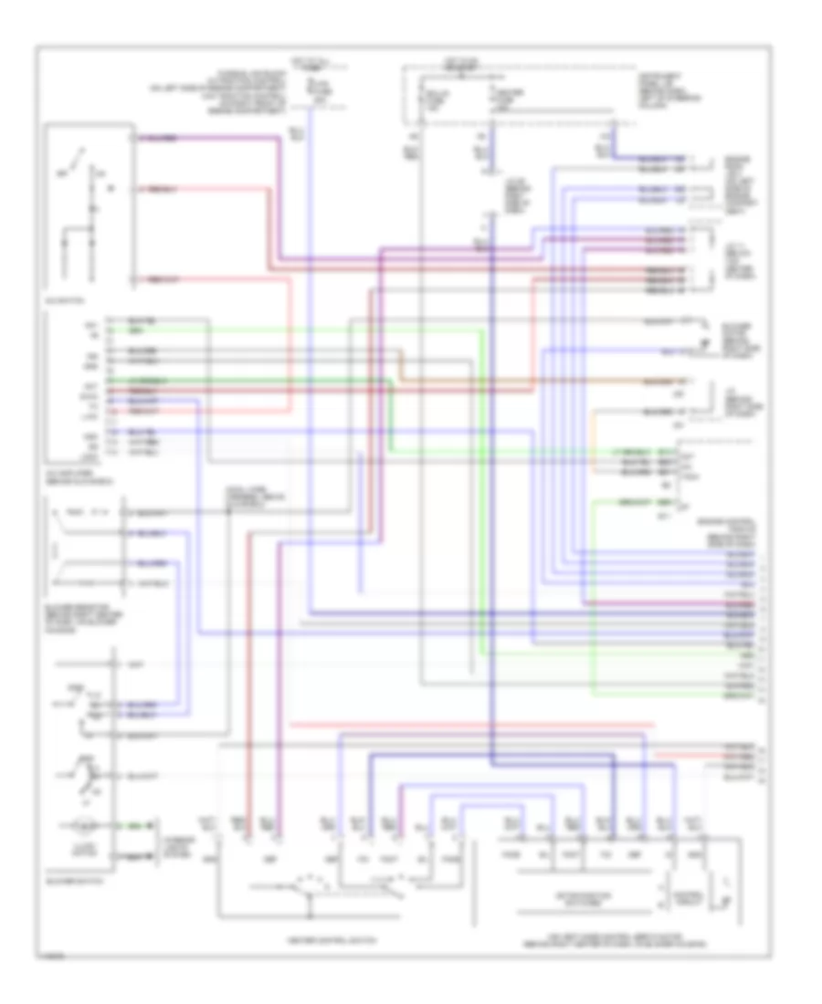
Automatic A/C Wiring Diagram (1 of 2) for Toyota Camry Solara SE 1999
List of elements for Automatic A/C Wiring Diagram (1 of 2) for Toyota Camry Solara SE 1999:
- (convertible: behind left side of dash)
- (coupe: below top center of dash)
- A/c
- A/c ambient temperature sensor (on front center of engine compartment)
- A/c control assembly (behind center of dash)
- A/c room temperature sensor (behind center of dash)
- A/c solar sensor (on upper left side of dash)
- A/c thermistor (behind right side of dash, on evaporator)
- A10
- A11
- A12
- A13
- A14
- A15
- A16
- A17
- A18
- A19
- A20
- A21
- A22
- A23
- A24
- A25
- A26
- Ac1
- Act
- Aif
- Air
- Air inlet control servo motor (behind right side of dash)
- Air mix control servo motor (behind center of dash, on blower housing)
- Air vent mode control servo motor (behind right center of dash, on blower housing)
- Amc
- Amh
- B/l
- B10
- B11
- B12
- B13
- B14
- B15
- B16
- B25
- B27
- Blw
- Control circuit
- Convertible
- Cool
- Coupe
- Def
- Defogger system
- E11
- E29
- Ecu-b fuse 10a
- Ecu-ig fuse 15a
- Engine control module (behind right side of dash)
- Engine room j/b 2 (on left side of engine compartment)
- F/d
- Face
- Foot
- Gnd
- Heater fuse 10a
- Hot at all times
- Hot in on or start
- Ig+
- Ign
- Illum
- Instrument cluster system
- Instrument panel j/b (behind dash, left of steering column)
- Interior lights system
- J/c
- J/c (behind right side of dash)
- J/c 1 (behind left kick panel)
- J/c 11 (below top center of dash)
- J/c 26 (behind right side of dash)
- J/c 29 (behind right side of dash)
- J24
- J25
- Lock
- Mgcr
- Motor position switches
- Pnk
- Psw
- Rdfg
- Red
- Spd
- Tach
- Tam
- Thwo
- Tpi
- V10
- Warm
Automatic A/C Wiring Diagram (2 of 2) for Toyota Camry Solara SE 1999
List of elements for Automatic A/C Wiring Diagram (2 of 2) for Toyota Camry Solara SE 1999:
- (cowl wire harness, above glove box) i5
- (cowl wire harness, behind top center of dash) i4
- (left radiator side support) g108
- (on right front of engine compartment) a/c triple pressure switch
- (right kick panel) g203
- A/c blower motor linear controller (behind center of dash)
- A/c condenser fan motor (on right front of engine compartment)
- A/c dual pressure switch
- A/c magnetic clutch & lock sensor (on left side of engine)
- A/c single pressure switch
- Blower motor (behind right side of dash)
- Blower resistor (behind right center of dash, on blower housing)
- Cds fuse 30a
- Diode (a/c) (in front of left front strut tower)
- E4 (engine room main wire harness, left front strut tower)
- Engine room j/b 2 (on left side of engine compartment)
- Engine room r/b 1 (on left side of engine compartment)
- Fan 1 relay
- Fan 2 relay
- Fan 3 relay
- Fusible link block (w/traction control) (on left side of engine compartment) (w/o traction control) (on right front of engine compartment)
- G202 (left instrument panel brace)
- Gnd
- Hot at all times
- Hot in or start
- Htr fuse 50a
- Htr relay
- Instrument panel j/b (behind dash, left of steering column)
- J/c (behind left side of dash)
- J/c 10
- J13
- Mg clt relay
- Radiator fan motor (on left front of engine compartment)
- Rdi fuse 30a
- Red
- Water temperature switch 1 (on right front of engine compartment)
- Water temperature switch 2 (on rear of engine)