AIR CONDITIONING
2.4L
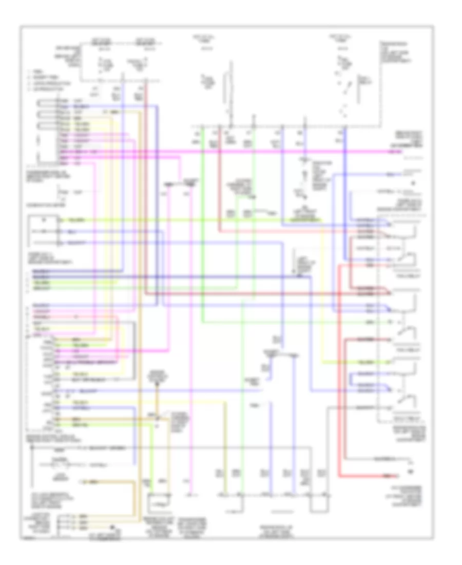
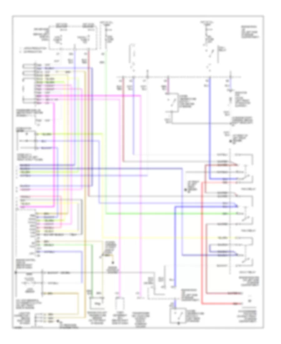
2.4L, Automatic A/C Wiring Diagram (1 of 2) for Toyota Camry XLE 2004

List of elements for 2.4L, Automatic A/C Wiring Diagram (1 of 2) for Toyota Camry XLE 2004:
- (at left kick panel) ii
- (at right dash reinforcement) in
- (left front of engine compartment) ec
- A/c ambient temperature sensor (at left front of engine compt)
- A/c control assembly (behind center of dash)
- A/c room temperature sensor (behind center of dash)
- A/c solar sensor (on top left side of dash)
- A/c thermistor (right side of dash)
- A/ci
- A/cs
- A14
- A26
- A54
- A56
- Ac1
- Aif
- Air
- Air inlet control servo motor (behind right side of dash)
- Air mix control servo motor (behind right side of dash)
- Air vent mode servo motor (behind center of dash)
- Amc
- Amh
- Aod
- Aof
- Blower motor (behind right side of dash)
- Blower motor controller (behind right side of dash)
- Blw
- Clock
- Data
- Def
- Defogger system
- Driver side j/b (behind left side of dash)
- Eb (right front of engine compartment)
- Ecu-b fuse 10a
- Engine room j/b (on left side of engine compartment)
- Engine room r/b (on left side of engine compartment)
- Exterior lights system interior lights system
- Face
- Gnd
- Hot at all times
- Htr fuse 50a
- Htr relay
- I2 (in dash harness, at right side of dash)
- Ig+
- Illum
- Interior lights system
- Mfrs
- Mrec
- Passenger side j/b (behind right center of dash)
- Pnk
- Pressure switch (right front of engine compartment)
- Psw
- Rdef
- S5-1
- S5-2
- S5-3
- Sg-1
- Sg-2
- Sg-3
- Sg-5
- Spd
- Sw1
- Tam
- Th+
- Tpi
- Tpm
- Tpo
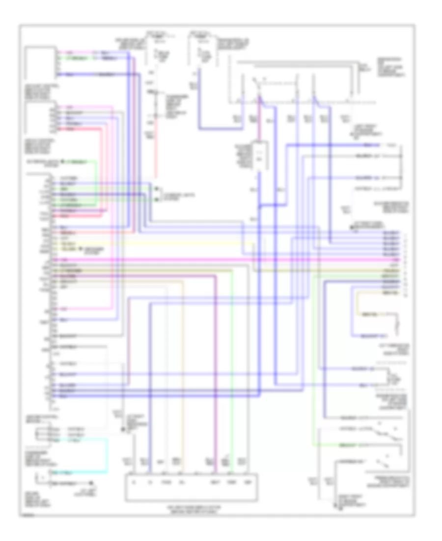
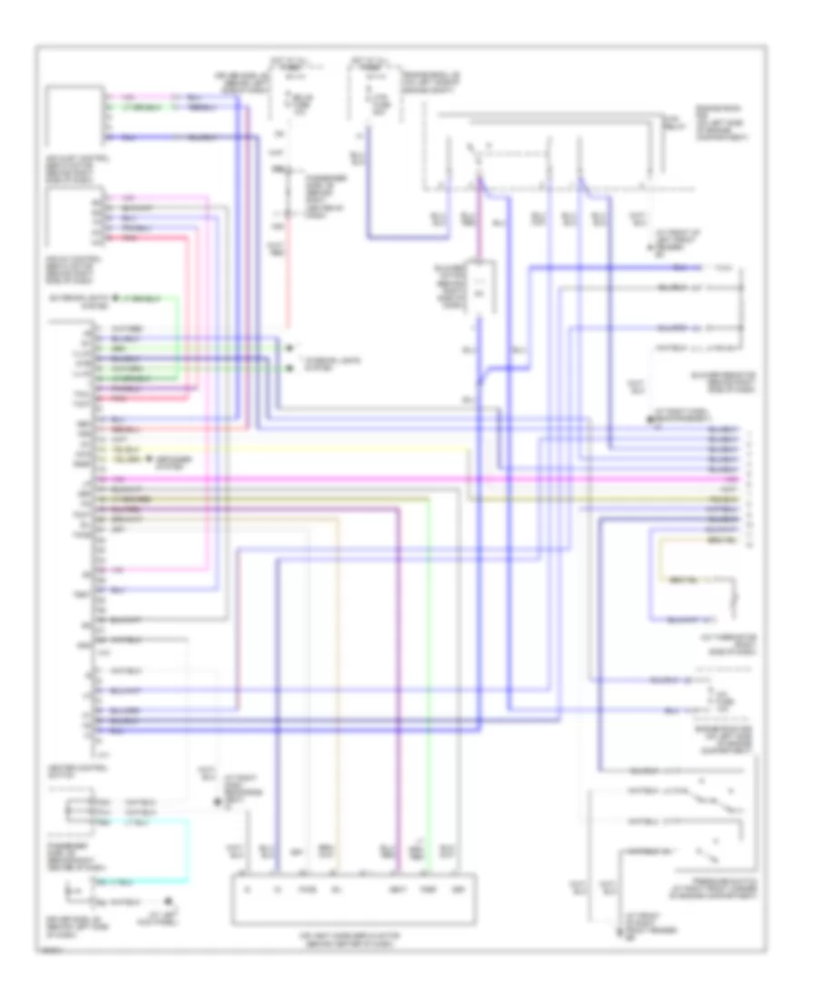
2.4L, Automatic A/C Wiring Diagram (2 of 2) for Toyota Camry XLE 2004
List of elements for 2.4L, Automatic A/C Wiring Diagram (2 of 2) for Toyota Camry XLE 2004:
- (behind right side of dash) theft deterrent ecu
- (in dash harness, at right side of dash)
- (in dash harness, at right side of dash) i8
- (left front of engine compt) ec
- (not used)
- A/c condenser fan motor (at front center of engine compartment)
- A/c lock sensor & a/c magnetic clutch (on left front side of engine)
- A/ci
- A/cs
- A22
- A29
- A36
- A59
- A82
- A92
- Acmg
- B118
- B124
- B125
- B129
- B14
- B34
- B44
- Cds fuse 30a
- Clutch
- Combination meter
- Diode (a/c 1) (left side of engine compartment)
- Diode (a/c 2) (left side of engine compartment)
- Driver side j/b (behind left side of dash)
- E10
- Ed (left front of engine compartment)
- Eg (at left side of cylinder bank)
- Engine control module (behind right side of dash)
- Engine controls system
- Engine coolant temperature sensor (on top rear of engine)
- Engine room j/b (on left side of engine compartment)
- Engine room j/b (on left side of engine compt)
- Engine room r/b (on left side of engine compartment)
- Except pzev
- Fan 1 relay
- Fan 2 relay
- Fan 3 relay
- Fan rly fuse 10a
- G24
- H10
- Hot at all times
- Hot in on or start
- Htr fuse 10a
- Imld
- Japan production
- Junction connector 1 (behind right side of dash)
- K10
- Lck1
- Lock sensor
- Mg clt relay
- Passenger side j/b (behind right center of dash)
- Pr2
- Pre
- Pzev
- Radiator fan motor (left front of engine compt)
- Rdi fuse 30a
- Red
- Spd
- Thr
- Thw
- Thwo
- Transponder key computer (on right side of steering column)
- Us production
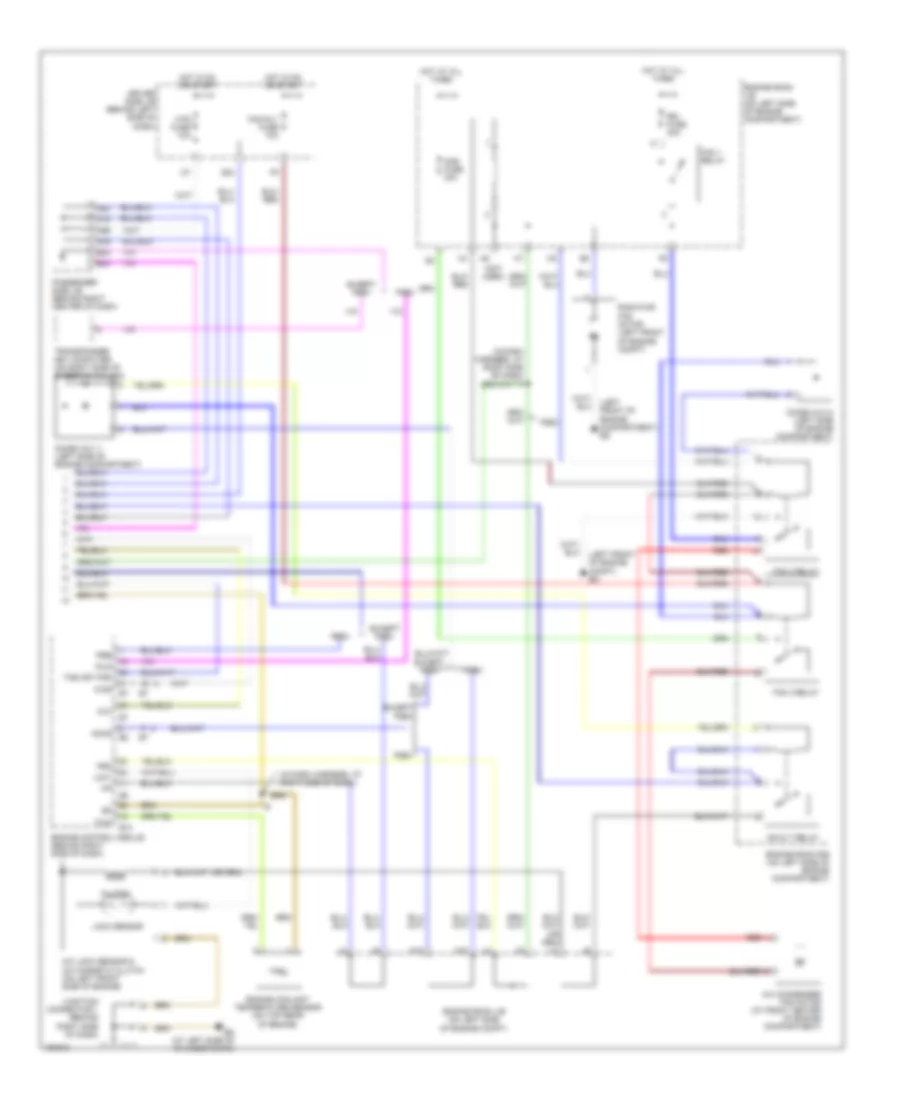
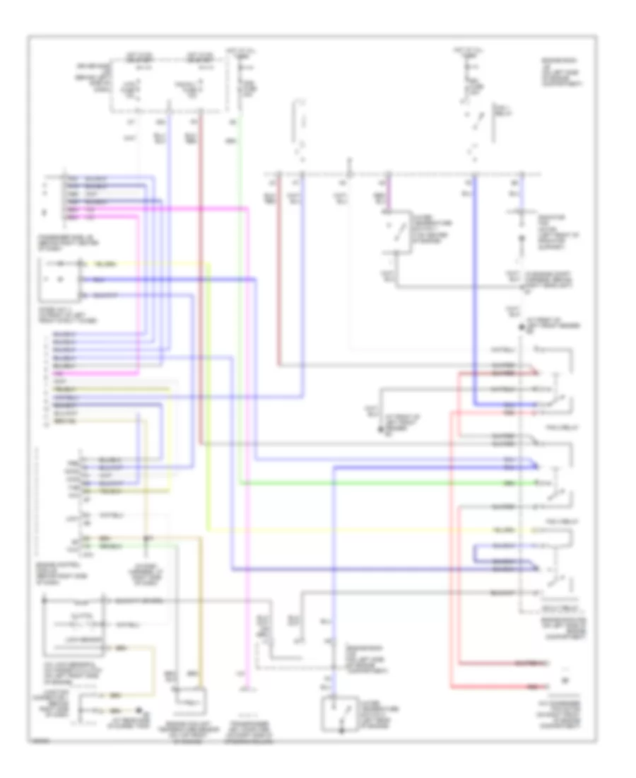
2.4L, Manual A/C Wiring Diagram (1 of 2) for Toyota Camry XLE 2004
List of elements for 2.4L, Manual A/C Wiring Diagram (1 of 2) for Toyota Camry XLE 2004:
- (at right dash reinforce- ment) in
- (at right dash reinforcement) in
- (left front of engine compartment) ec
- (right front of engine compartment) eb
- A/c
- A/c fuse 10a
- A/c thermistor (right side of dash)
- A/cb
- A14
- A34
- A36
- A64
- A66
- Acid
- Air inlet control servo motor (behind right side of dash)
- Air mix control servo motor (behind right side of dash)
- Air vent mode servo motor (behind center of dash)
- B/l
- Blower motor (behind right side of dash)
- Blower resistor (behind right side of dash)
- Def
- Defogger system
- Driver side j/b (behind left side of dash)
- Ecu-b fuse 10a
- Engine room j/b (on left side of engine compt)
- Engine room r/b (on left side of engine compartment)
- Exterior lights system
- F/d
- Face
- Fdef
- Foot
- Frs
- Gnd
- H10
- H11
- Heat
- Heater control switch
- Hot at all times
- Htr fuse 50a
- Htr relay
- Ig+
- Ii (at left kick panel)
- Illum
- Interior lights system
- Passenger side j/b (behind right center of dash)
- Pnk
- Pressure switch (right front of engine compartment)
- Rdef
- Rec
- Tcol
- Test
- Thot
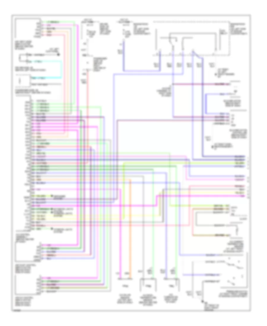
2.4L, Manual A/C Wiring Diagram (2 of 2) for Toyota Camry XLE 2004
List of elements for 2.4L, Manual A/C Wiring Diagram (2 of 2) for Toyota Camry XLE 2004:
- (in dash harness, at right side of dash)
- (left front of engine compartment) ed
- (left front of engine compt) ec
- (not used)
- A/c condenser fan motor (at front center of engine compartment)
- A/c lock sensor & a/c magnetic clutch (on left front side of engine)
- A/ci
- A/cs
- A19
- A20
- A39
- A69
- Acmg
- B24
- B34
- Cds fuse 30a
- Clutch
- Diode (a/c 1) (left side of engine compartment)
- Diode (a/c 2) (left side of engine compartment)
- Driver side j/b (behind left side of dash)
- E10
- Eg (at left side of cylinder bank)
- Engine control module (behind right side of dash)
- Engine coolant temperature sensor (on top rear of engine)
- Engine room j/b (on left side of engine compartment)
- Engine room j/b (on left side of engine compt)
- Engine room r/b (on left side of engine compartment)
- Except pzev
- Fan 1 relay
- Fan 2 relay
- Fan 3 relay
- Fan rly fuse 10a
- G24
- H10
- Hot at all times
- Hot in on or start
- Htr fuse 10a
- Imld
- Junction connector 1 (behind right side of dash)
- K10
- Lck1
- Lock sensor
- Mg clt relay
- Passenger side j/b (behind right center of dash)
- Pr2
- Pre
- Pzev
- Radiator fan motor (left front of engine compt)
- Rdi fuse 30a
- Red
- The (or thr)
- Thw
- Transponder key computer (on right side of steering column)
3.0L
3.0L, Automatic A/C Wiring Diagram (1 of 2) for Toyota Camry XLE 2004
List of elements for 3.0L, Automatic A/C Wiring Diagram (1 of 2) for Toyota Camry XLE 2004:
- (at front of left front fender) ec
- (at left kick panel) ii
- (at right dash reinforcement) in
- A/c ambient temperature sensor (at left front of engine compt)
- A/c control assembly (behind center of dash)
- A/c room temperature sensor (behind center of dash)
- A/c solar sensor (on top left side of dash)
- A/c thermistor (right side of dash)
- A/ci
- A/cs
- A14
- A26
- A54
- A56
- Ac1
- Aif
- Air
- Air inlet control servo motor (behind right side of dash)
- Air mix control servo motor (behind right side of dash)
- Air vent mode servo motor (behind center of dash)
- Amc
- Amh
- Aod
- Aof
- Blower motor (behind right side of dash)
- Blower motor controller (behind right side of dash)
- Blw
- Clock
- Data
- Def
- Defogger system
- Driver side j/b (behind left side of dash)
- Eb (at front of right front fender)
- Ecu-b fuse 10a
- Engine room j/b (on left side of engine compartment)
- Engine room r/b (on left side of engine compartment)
- Exterior lights system interior lights system
- Face
- Gnd
- Hot at all times
- Htr fuse 50a
- Htr relay
- I2 (in dash harness, at right side of dash)
- Ig+
- Illum
- Interior lights system
- Mfrs
- Mrec
- Passenger side j/b (behind right center of dash)
- Pnk
- Pressure switch (at right front corner of engine compartment)
- Psw
- Rdef
- S5-1
- S5-2
- S5-3
- Sg-1
- Sg-2
- Sg-3
- Sg-5
- Spd
- Sw1
- Tam
- Th+
- Tpi
- Tpm
- Tpo
3.0L, Automatic A/C Wiring Diagram (2 of 2) for Toyota Camry XLE 2004
List of elements for 3.0L, Automatic A/C Wiring Diagram (2 of 2) for Toyota Camry XLE 2004:
- (at front of left front fender) ec
- (at front of left front fender) ed
- (in dash harness, at right side of dash)
- (in engine compt harness, behind right headlight) e1
- A/c condenser fan motor (on right front of engine compartment)
- A/c lock sensor & a/c magnetic clutch (on left front side of engine)
- A/ci
- A/cs
- A22
- A29
- A36
- A59
- A82
- A92
- Acmg
- B118
- B124
- B125
- B129
- B14
- B34
- B44
- Cds fuse 30a
- Clutch
- Combination meter
- Diode (a/c 1) (in front of left front strut tower)
- Driver side j/b (behind left side of dash)
- E10
- Ef (at rear side of surge tank)
- Engine control module (behind right side of dash)
- Engine controls system
- Engine coolant temperature sensor (on top front of engine)
- Engine room j/b (on left side of engine compartment)
- Engine room r/b (on left side of engine compartment)
- Fan 1 relay
- Fan 2 relay
- Fan 3 relay
- Fan rly fuse 10a
- G24
- Hot at all times
- Hot in on or start
- Htr fuse 10a
- Japan production
- Junction connector 1 (behind right side of dash)
- Lck1
- Lock sensor
- Mg clt relay
- Passenger side j/b (behind right center of dash)
- Pre
- Radiator fan motor (left front of radiator support)
- Rdi fuse 30a
- Red
- Spd
- Theft deterrent ecu (behind right side of dash)
- Thr
- Thw
- Thwo
- Transponder key computer (on right side of steering column)
- Us production
- Water temperature switch 1 (top center of engine)
- Water temperature switch 2 (left rear of engine)
3.0L, Manual A/C Wiring Diagram (1 of 2) for Toyota Camry XLE 2004
List of elements for 3.0L, Manual A/C Wiring Diagram (1 of 2) for Toyota Camry XLE 2004:
- (at front of left front fender) ec
- (at front of right front fender) eb
- (at right dash reinforce- ment) in
- (at right dash reinforcement) in
- A/c
- A/c fuse 10a
- A/c thermistor (right side of dash)
- A/cb
- A14
- A34
- A36
- A64
- A66
- Acid
- Air inlet control servo motor (behind right side of dash)
- Air mix control servo motor (behind right side of dash)
- Air vent mode servo motor (behind center of dash)
- B/l
- Blower motor (behind right side of dash)
- Blower resistor (behind right side of dash)
- Def
- Defogger system
- Driver side j/b (behind left side of dash)
- Ecu-b fuse 10a
- Engine room j/b (on left side of engine compt)
- Engine room r/b (on left side of engine compartment)
- Exterior lights system
- F/d
- Face
- Fdef
- Foot
- Frs
- Gnd
- H10
- H11
- Heat
- Heater control switch
- Hot at all times
- Htr fuse 50a
- Htr relay
- Ig+
- Ii (at left kick panel)
- Illum
- Interior lights system
- Passenger side j/b (behind right center of dash)
- Pnk
- Pressure switch (at right front corner of engine compartment)
- Rdef
- Rec
- Tcol
- Test
- Thot
3.0L, Manual A/C Wiring Diagram (2 of 2) for Toyota Camry XLE 2004
List of elements for 3.0L, Manual A/C Wiring Diagram (2 of 2) for Toyota Camry XLE 2004:
- (at front of left front fender) ec
- (at front of left front fender) ed
- (in dash harness, at right side of dash)
- A/c condenser fan motor (on right front of engine compartment)
- A/c lock sensor & a/c magnetic clutch (on left front side of engine)
- A/ci
- A/cs
- A19
- A20
- A39
- A69
- Acmg
- B24
- B34
- Cds fuse 30a
- Clutch
- Diode (a/c 1) (in front of left front strut tower)
- Driver side j/b (behind left side of dash)
- E10
- Ef (at rear side of surge tank)
- Engine control module (behind right side of dash)
- Engine coolant temperature sensor (on top front of engine)
- Engine room j/b (on left side of engine compartment)
- Engine room r/b (on left side of engine compartment)
- Fan 1 relay
- Fan 2 relay
- Fan 3 relay
- Fan rly fuse 10a
- G24
- Hot at all times
- Hot in on or start
- Htr fuse 10a
- Junction connector 1 (behind right side of dash)
- Lck1
- Lock sensor
- Mg clt relay
- Passenger side j/b (behind right center of dash)
- Pre
- Radiator fan motor (left front of radiator support)
- Rdi fuse 30a
- Red
- The
- Thw
- Transponder key computer (on right side of steering column)
- Water temperature switch 1 (top center of engine)
- Water temperature switch 2 (left rear of engine)
3.3L
3.3L, Automatic A/C Wiring Diagram (1 of 2) for Toyota Camry XLE 2004
List of elements for 3.3L, Automatic A/C Wiring Diagram (1 of 2) for Toyota Camry XLE 2004:
- (at front of left front fender) ec
- (at left kick panel) ii
- (at right dash reinforcement) in
- A/c ambient temperature sensor (at left front of engine compt)
- A/c control assembly (behind center of dash)
- A/c room temperature sensor (behind center of dash)
- A/c solar sensor (on top left side of dash)
- A/c thermistor (right side of dash)
- A/ci
- A/cs
- A14
- A26
- A54
- A56
- Ac1
- Aif
- Air
- Air inlet control servo motor (behind right side of dash)
- Air mix control servo motor (behind right side of dash)
- Air vent mode servo motor (behind center of dash)
- Amc
- Amh
- Aod
- Aof
- Blower motor (behind right side of dash)
- Blower motor controller (behind right side of dash)
- Blw
- Clock
- Data
- Def
- Defogger system
- Driver side j/b (behind left side of dash)
- Eb (at front of right front fender)
- Ecu-b fuse 10a
- Engine room j/b (on left side of engine compartment)
- Engine room r/b (on left side of engine compartment)
- Exterior lights system interior lights system
- Face
- Gnd
- Hot at all times
- Htr fuse 50a
- Htr relay
- I2 (in dash harness, at right side of dash)
- Ig+
- Illum
- Interior lights system
- Mfrs
- Mrec
- Passenger side j/b (behind right center of dash)
- Pnk
- Pressure switch (at right front corner of engine compartment)
- Psw
- Rdef
- S5-1
- S5-2
- S5-3
- Sg-1
- Sg-2
- Sg-3
- Sg-5
- Spd
- Sw1
- Tam
- Th+
- Tpi
- Tpm
- Tpo
3.3L, Automatic A/C Wiring Diagram (2 of 2) for Toyota Camry XLE 2004
List of elements for 3.3L, Automatic A/C Wiring Diagram (2 of 2) for Toyota Camry XLE 2004:
- (at front of left front fender) ec
- (at front of left front fender) ed
- (in dash harness, at right side of dash)
- (in engine compt harness, behind right headlight) e1
- A/c condenser fan motor (on right front of engine compartment)
- A/c lock sensor & a/c magnetic clutch (on left front side of engine)
- A/ci
- A/cs
- A22
- A29
- A36
- A59
- A82
- A92
- Acmg
- B118
- B124
- B125
- B129
- B14
- B34
- B44
- Cds fuse 30a
- Clutch
- Combination meter
- Diode (a/c 1) (in front of left front strut tower)
- Driver side j/b (behind left side of dash)
- E10
- Ef (at rear side of surge tank)
- Engine control module (behind right side of dash)
- Engine controls system
- Engine coolant temperature sensor (on top front of engine)
- Engine room j/b (on left side of engine compartment)
- Engine room r/b (on left side of engine compartment)
- Fan 1 relay
- Fan 2 relay
- Fan 3 relay
- Fan rly fuse 10a
- G24
- Hot at all times
- Hot in on or start
- Htr fuse 10a
- Japan production
- Junction connector 1 (behind right side of dash)
- Lck1
- Lock sensor
- Mg clt relay
- Passenger side j/b (behind right center of dash)
- Pre
- Radiator fan motor (left front of radiator support)
- Rdi fuse 30a
- Red
- Spd
- Theft deterrent ecu (behind right side of dash)
- Thr
- Thw
- Thwo
- Transponder key computer (on right side of steering column)
- Us production
- Water temperature switch 1 (top center of engine)
- Water temperature switch 2 (left rear of engine)
3.3L, Manual A/C Wiring Diagram (1 of 2) for Toyota Camry XLE 2004
List of elements for 3.3L, Manual A/C Wiring Diagram (1 of 2) for Toyota Camry XLE 2004:
- (at front of left front fender) ec
- (at front of right front fender) eb
- (at right dash reinforce- ment) in
- (at right dash reinforcement) in
- A/c
- A/c fuse 10a
- A/c thermistor (right side of dash)
- A/cb
- A14
- A34
- A36
- A64
- A66
- Acid
- Air inlet control servo motor (behind right side of dash)
- Air mix control servo motor (behind right side of dash)
- Air vent mode servo motor (behind center of dash)
- B/l
- Blower motor (behind right side of dash)
- Blower resistor (behind right side of dash)
- Def
- Defogger system
- Driver side j/b (behind left side of dash)
- Ecu-b fuse 10a
- Engine room j/b (on left side of engine compt)
- Engine room r/b (on left side of engine compartment)
- Exterior lights system
- F/d
- Face
- Fdef
- Foot
- Frs
- Gnd
- H10
- H11
- Heat
- Heater control switch
- Hot at all times
- Htr fuse 50a
- Htr relay
- Ig+
- Ii (at left kick panel)
- Illum
- Interior lights system
- Passenger side j/b (behind right center of dash)
- Pnk
- Pressure switch (at right front corner of engine compartment)
- Rdef
- Rec
- Tcol
- Test
- Thot
3.3L, Manual A/C Wiring Diagram (2 of 2) for Toyota Camry XLE 2004
List of elements for 3.3L, Manual A/C Wiring Diagram (2 of 2) for Toyota Camry XLE 2004:
- (at front of left front fender) ec
- (at front of left front fender) ed
- (in dash harness, at right side of dash)
- A/c condenser fan motor (on right front of engine compartment)
- A/c lock sensor & a/c magnetic clutch (on left front side of engine)
- A/ci
- A/cs
- A19
- A20
- A39
- A69
- Acmg
- B24
- B34
- Cds fuse 30a
- Clutch
- Diode (a/c 1) (in front of left front strut tower)
- Driver side j/b (behind left side of dash)
- E10
- Ef (at rear side of surge tank)
- Engine control module (behind right side of dash)
- Engine coolant temperature sensor (on top front of engine)
- Engine room j/b (on left side of engine compartment)
- Engine room r/b (on left side of engine compartment)
- Fan 1 relay
- Fan 2 relay
- Fan 3 relay
- Fan rly fuse 10a
- G24
- Hot at all times
- Hot in on or start
- Htr fuse 10a
- Junction connector 1 (behind right side of dash)
- Lck1
- Lock sensor
- Mg clt relay
- Passenger side j/b (behind right center of dash)
- Pre
- Radiator fan motor (left front of radiator support)
- Rdi fuse 30a
- Red
- The
- Thw
- Transponder key computer (on right side of steering column)
- Water temperature switch 1 (top center of engine)
- Water temperature switch 2 (left rear of engine)