AIR CONDITIONING
Heater Wiring Diagram for Toyota Corolla CE 2002

List of elements for Heater Wiring Diagram for Toyota Corolla CE 2002:
- (behind center of dash) center j/b
- (behind glove box) air inlet control servo motor
- (dash wire harn, top center of dash) i6
- (front side of right fender) ea
- Blower motor (below right side of dash, in heater-a/c housing)
- Blower resistor (below right side of dash, in heater-a/c housing)
- Blower switch
- C13
- C14
- C15
- Center j/b (behind center of dash)
- D12
- Engine room r/b 6 (on right front of engine compartment, on radiator support)
- Fresh
- Gauge fuse 10a
- Heater control switch (rear window defogger switch)
- Hot at all times
- Hot in on or start
- Htr fuse 50a
- Htr relay
- Ie (left dash brace)
- Ih (right kick panel)
- Instrument panel j/b (behind left side of dash, at lower finish panel)
- Integration relay
- J/c 14
- J/c 8
- Me1
- Me2
- Off
- Recir
- Red
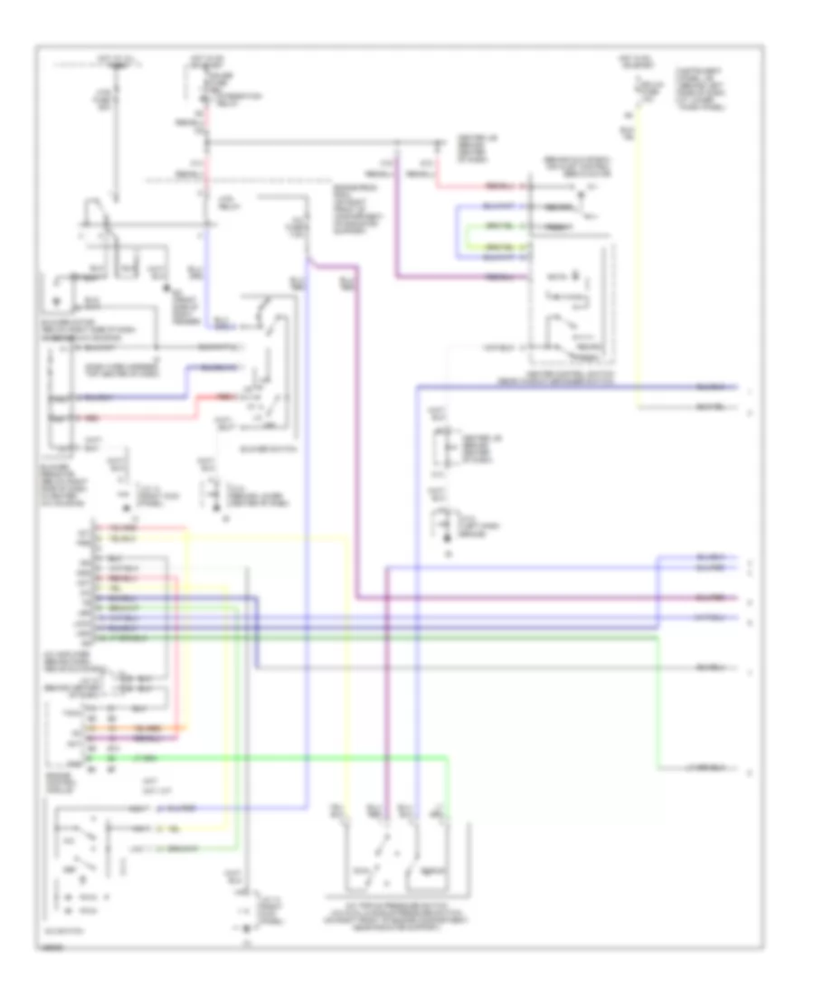
Manual A/C Wiring Diagram (1 of 2) for Toyota Corolla CE 2002
List of elements for Manual A/C Wiring Diagram (1 of 2) for Toyota Corolla CE 2002:
- (behind glove box) air inlet control servo motor
- 3a/t, m/t
- 4a/t
- A/c
- A/c amplifier (behind dash, above glove box)
- A/c fuse 7.5a
- A/c switch
- A/c triple pressure switch (a/c dual & single pressure switch) (on right front of engine compartment, near radiator support)
- A/c+
- Ac1
- Act
- Blower motor (below right side of dash, in heater-a/c housing)
- Blower resistor (below right side of dash, in heater- a/c housing)
- Blower switch
- C13
- C14
- C15
- Center j/b (behind center of dash)
- D12
- Def
- Dual
- E10
- Ea (front side of right fender)
- Ecu-ig fuse 10a
- Engine control module
- Engine room r/b 6 (on right front of compartment, on radiator support)
- Fan
- Fresh
- Gauge fuse 10a
- Gnd
- Heater control switch (rear window defogger switch)
- Hot at all times
- Hot in on
- Hot in on or start
- Htr fuse 50a
- Htr relay
- I6 (dash wire harness, top center of dash)
- Ign
- Instrument panel j/b (behind left side of dash, at lower finish panel)
- Integration relay
- J/c 10 (behind center of dash)
- J/c 14 (right kick panel)
- J/c 8 (behind lower center of dash)
- J/c 8 (left dash brace)
- La/c
- Led
- Lock
- Me1
- Me2
- Mgc
- Off
- Or start
- Prs
- Recirc
- Red
- Single
- Tach
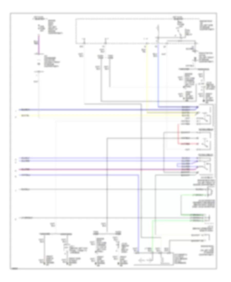
Manual A/C Wiring Diagram (2 of 2) for Toyota Corolla CE 2002
List of elements for Manual A/C Wiring Diagram (2 of 2) for Toyota Corolla CE 2002:
- (engine room main wire harness, at top of left kick panel) i1
- (front side of left fender) eb
- (front side of right fender) ea
- A/c condenser fan motor (on right front of engine compartment)
- A/c evaporator temperature sensor (behind right side of dash, on evaporator)
- A/c magnetic clutch & lock sensor (on a/c compresor)
- Ac fan 2 relay
- Ac fan 3 relay
- Ac mg relay
- Cds fuse 30a
- E10
- Engine room j/b (on left side of engine compartment)
- Engine room r/b 5 (on left front of engine compartment)
- Fan no.1 relay
- Hot in on
- J/c 1 (behind left kick panel, taped to harness)
- J/c 13 (behind upper right side of dash)
- J/c 20 (behind left end of dash)
- Nummi made
- Or start
- Radiator fan motor (on left front of engine compartment)
- Rdi fuse 30a
- Tmmc made