AIR CONDITIONING
Manual A/C Wiring Diagram (1 of 2) for Toyota Matrix 2005

List of elements for Manual A/C Wiring Diagram (1 of 2) for Toyota Matrix 2005:
- (in instrument panel harness, behind upper left side of dash) i5
- (integral to right j/b) right r/b
- A/c fuse 10a
- A/c switch
- A/c switch & air inlet control switch
- A11
- A20
- Air inlet control switch
- Air inlet servo control motor (behind glove box)
- B12
- B22
- Blower motor (below right side of dash, in heater-a/c housing)
- Blower resistor (below right side of dash, in heater-a/c housing)
- Blower switch
- Defroster mode switch (w/o navigation)
- Dome fuse 15a
- Engine room r/b (integral to engine room j/b)
- Fresh
- Gauge fuse 10a
- Heater fuse 40a
- High
- Hot at all times
- Hot in on or start
- Htr relay
- I10 (in instrument panel harness, behind right end of dash)
- I9 (in instrument panel harness, behind right end of dash)
- Illum
- Instrument panel j/b (behind left side of dash)
- Interior lights system
- Junction connector (at right kick panel)
- Junction connector 7 (at right kick panel)
- Low
- Off
- Pnk
- Recirc
- Red
- Right j/b (behind upper right side of dash)
- W/ navigation
- W/o navigation
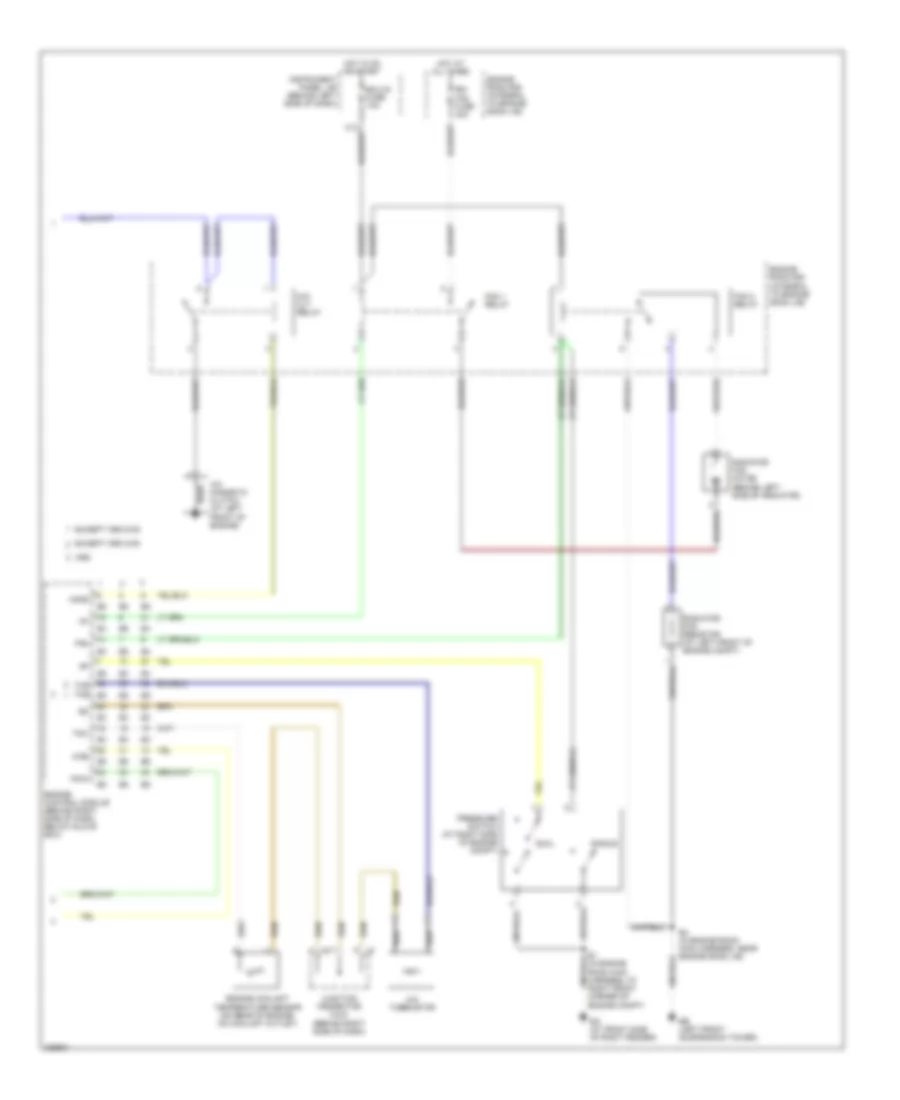
Manual A/C Wiring Diagram (2 of 2) for Toyota Matrix 2005
List of elements for Manual A/C Wiring Diagram (2 of 2) for Toyota Matrix 2005:
- (in engine room main harness, at right front corner of engine compt)
- A/c magnetic clutch (at left front of engine)
- A/c thermistor
- A/cs
- Acld
- Acmg
- Dual
- E4 (in engine room main harness, near engine room j/b)
- Ea (at front side of right fender)
- Eb (left front suspension tower)
- Ecu-ig fuse 10a
- Engine control module (behind right side of dash, below glove box)
- Engine coolant temperature sensor (on rear of engine, on coolant outlet)
- Engine room r/b (integral to engine room j/b)
- Except xrs 2wd
- Except xrs 4wd
- Fan
- Fan 1 relay
- Fan 2 relay
- Hot at all times
- Hot in on or start
- Instrument panel j/b (behind left side of dash)
- J5 f
- J6 h
- Junction connector 5 & 6 (behind right side of dash)
- M/g clt relay
- Pressure switch (at right side of engine compt)
- Radiator fan motor (behind left side of radiator)
- Radiator fan resistor (at left front of engine compt)
- Rdi fan fuse 40a
- Single
- The e5
- Thr
- Thw
- Xrs