AIR CONDITIONING
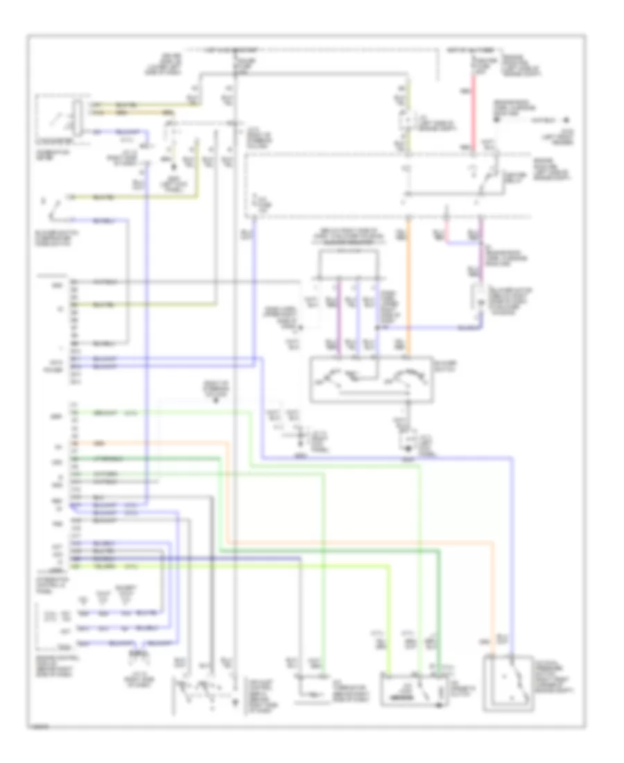
A/C Wiring Diagram for Toyota Tundra SR5 2000

List of elements for A/C Wiring Diagram for Toyota Tundra SR5 2000:
- (3.4l) (4.7l)
- (4.7l)
- (below right side of dash, in blower housing) blower resistor
- (dash harn, upper right side of dash i16
- (dash harn, upper right side of dash) i4
- (engine room harn, in engine room r/b) e3
- (right of steering column) i2
- 4.7l
- A/c dual pressure switch (right front corner of engine compt)
- A/c fuse 10a
- A/c lock sensor
- A/c magnetic clutch
- A/c thermistor (behind right side of dash)
- A10
- A11
- A12
- A13
- A14
- A15
- A16
- A17
- A18
- A19
- A20
- A21
- A3 (4.7l)
- Ac+2
- Ac1 a/c
- Ac2
- Act
- Air inlet control servo (behind right side of dash)
- B1 (3.4l)
- B10
- B11
- B12
- B13
- B14
- B25
- Blower motor (below right side of dash, in blower housing)
- Blower switch
- Blower switch & defroster mode switch
- Calif 3.4l
- Combination meter
- Driver side j/b (lower left side of dash)
- E1 (engine room harn, in engine room r/b)
- Engine control module (behind right side of dash)
- Engine room r/b (left side of engne compt)
- Except calif 3.4l
- Frs
- G102 (left front fender)
- G200
- G200 (left kick panel)
- G203
- Gauge fuse 10a
- Gnd
- Heater fuse 50a
- Heater relay
- Hot at all times
- Hot in on or start
- Ig+
- Ig-
- Integraton control & panel
- J/c (left side of engine compt)
- J/c 12 (right side of dash)
- J/c 13 (right kick panel)
- J/c 3 (left kick panel)
- J/c 8 (right of steering column)
- Lock
- Mgc
- Off
- Power
- Rec
- Red
- Ssr-
- Tach
- Tachometer
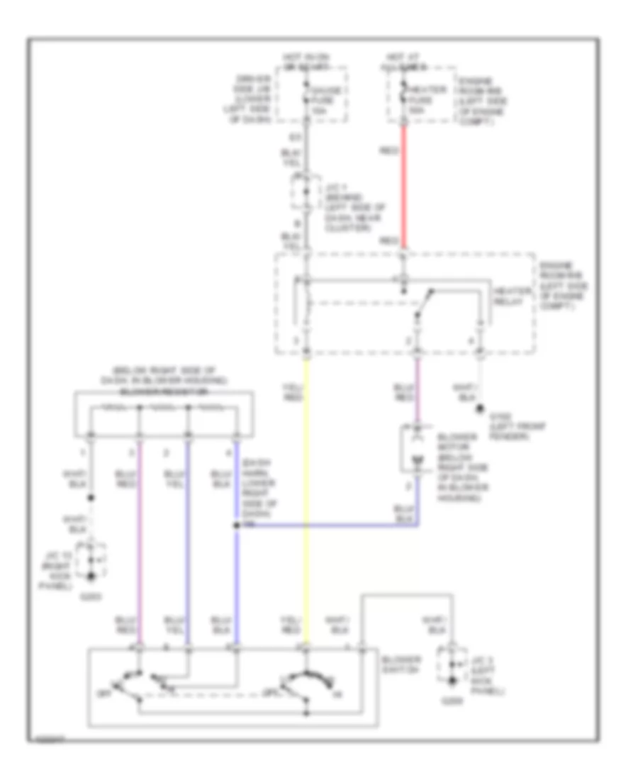
Heater Wiring Diagram for Toyota Tundra SR5 2000
List of elements for Heater Wiring Diagram for Toyota Tundra SR5 2000:
- (below right side of dash, in blower housing) blower resistor
- (dash harn, lower right side of dash) i16
- Blower motor (below right side of dash, in blower housing)
- Blower switch
- Driver side j/b (lower left side of dash)
- Engine room r/b (left side of engne compt)
- G102 (left front fender)
- G200
- G203
- Gauge fuse 10a
- Heater fuse 50a
- Heater relay
- Hot at all times
- Hot in on or start
- J/c 1 (behind left side of dash, near cluster)
- J/c 13 (right kick panel)
- J/c 3 (left kick panel)
- Off
- Red
Manual A/C Wiring Diagram for Toyota Tundra SR5 2000
List of elements for Manual A/C Wiring Diagram for Toyota Tundra SR5 2000:
- (3.4l) (4.7l)
- (4.7l)
- (below right side of dash, in blower housing) blower resistor
- (dash harn, upper right side of dash i16
- (dash harn, upper right side of dash) i4
- (engine room harn, in engine room r/b) e3
- (right of steering column) i2
- 4.7l
- A/c dual pressure switch (right front corner of engine compt)
- A/c fuse 10a
- A/c lock sensor
- A/c magnetic clutch
- A/c thermistor (behind right side of dash)
- A10
- A11
- A12
- A13
- A14
- A15
- A16
- A17
- A18
- A19
- A20
- A21
- A3 (4.7l)
- Ac+2
- Ac1 a/c
- Ac2
- Act
- Air inlet control servo (behind right side of dash)
- B1 (3.4l)
- B10
- B11
- B12
- B13
- B14
- B25
- Blower motor (below right side of dash, in blower housing)
- Blower switch
- Blower switch & defroster mode switch
- Calif 3.4l
- Combination meter
- Driver side j/b (lower left side of dash)
- E1 (engine room harn, in engine room r/b)
- Engine control module (behind right side of dash)
- Engine room r/b (left side of engne compt)
- Except calif 3.4l
- Frs
- G102 (left front fender)
- G200
- G200 (left kick panel)
- G203
- Gauge fuse 10a
- Gnd
- Heater fuse 50a
- Heater relay
- Hot at all times
- Hot in on or start
- Ig+
- Ig-
- Integraton control & panel
- J/c (left side of engine compt)
- J/c 12 (right side of dash)
- J/c 13 (right kick panel)
- J/c 3 (left kick panel)
- J/c 8 (right of steering column)
- Lock
- Mgc
- Off
- Power
- Rec
- Red
- Ssr-
- Tach
- Tachometer