AIR CONDITIONING
2.8L
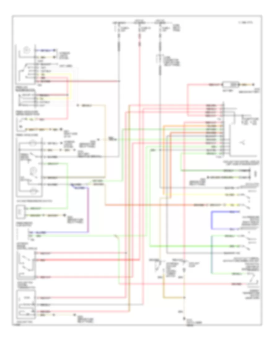
2.8L, Air Conditioning Wiring Diagrams for Volkswagen GTI VR6 1995
List of elements for 2.8L, Air Conditioning Wiring Diagrams for Volkswagen GTI VR6 1995:
- (not used)
- 1995 vftc c
- A/c and fresh/recirc switch
- A/c clutch
- A/c cut out thermal switch/third speed coolant
- A/c pressure switch (right side of engine compt)
- A/c switch
- A1/5
- After-run coolant fan control thermo- switch
- Ambient temperature switch (near horn)
- Battery
- Coolant fan
- Coolant fan control module (left side of engine compt)
- Coolant fan control thermoswitch
- Coolant pump
- D/3
- Fan switch (center of engine compt)
- Fresh air blower
- Fresh air blower series resistance
- Fresh air blower switch
- Fresh/ recirc switch
- Fresh/recirc flap switch
- Fuse 19 30a
- Fuse 30a
- Fuse 4 15a
- Fuse 50a
- Fuse 6 30a
- Fuse/ relay panel
- G100 (behind battery)
- G133 (on cylinder head)
- G201 (right side of i/p)
- G202 (beside fuse/ relay panel)
- Hot at all times
- Hot in run
- Interior lights system
- Motronic engine control module
- Nca
- Q/2
- Red
- T10a
- T2pp
- T41
- T68
- T6g
- Wire connector (above fuse/ relay panel)
 English