AIR CONDITIONING
Automatic A/C Wiring Diagram (1 of 2) for Volkswagen Jetta GL 1999

List of elements for Automatic A/C Wiring Diagram (1 of 2) for Volkswagen Jetta GL 1999:
- (at base of windshield, in center of plenum) motronic engine control module
- Air flow flap motor and position sensor
- Central flap motor and position sensor
- Climatronic control module
- Footwell/defroster flap
- Fresh air blower
- Fresh air motor control module
- Fuse 25a
- Fuse 7.5a
- Fuse panel (behind left side of dash)
- G201 (lower right "a" pillar)
- G203 (lower right "a" pillar)
- Hot in run and start
- Hot w/ load reduction relay energized
- Indicator unit control module
- Interior lights system
- Motor and position sensor
- On board diagnostic connector (under left side of dash)
- Sunlight photo sensor
- T12
- T121
- T16a
- T16b
- T20
- T32
- T32a
- Temp regulator flap motor and position sensor
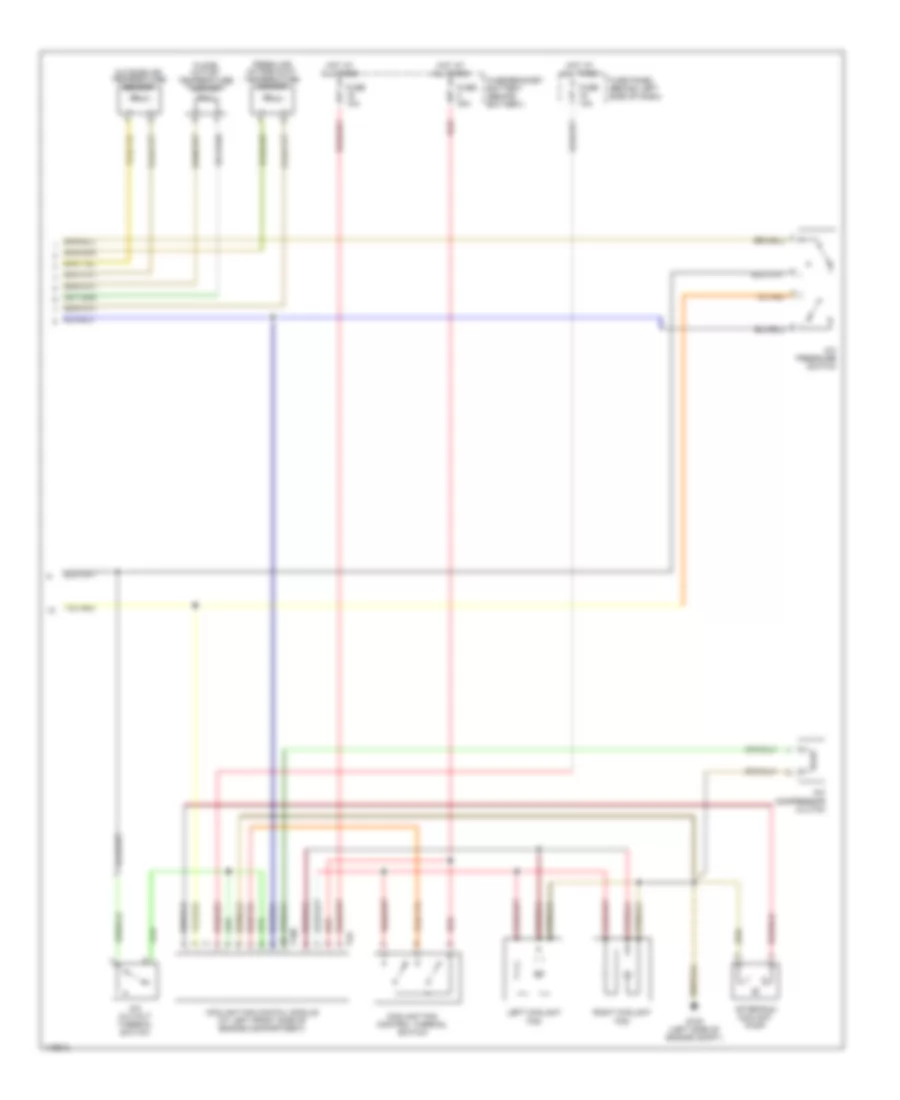
Automatic A/C Wiring Diagram (2 of 2) for Volkswagen Jetta GL 1999
List of elements for Automatic A/C Wiring Diagram (2 of 2) for Volkswagen Jetta GL 1999:
- A/c compressor clutch
- A/c cut-out thermal switch
- A/c pressure switch
- After-run coolant pump
- Coolant fan contol module (at left front side of engine compartment)
- Coolant fan control thermal switch
- Floor outlet temperature sender
- Fresh air intake duct temperature sensor
- Fuse 10a
- Fuse 30a
- Fuse panel (behind left side of dash)
- Fuse/bracket battery (behind battery)
- G100 (left side of engine compt)
- Hot at all times
- Left coolant fan
- Outside air temperature sensor
- Red
- Right coolant fan
- T10b
- T4a
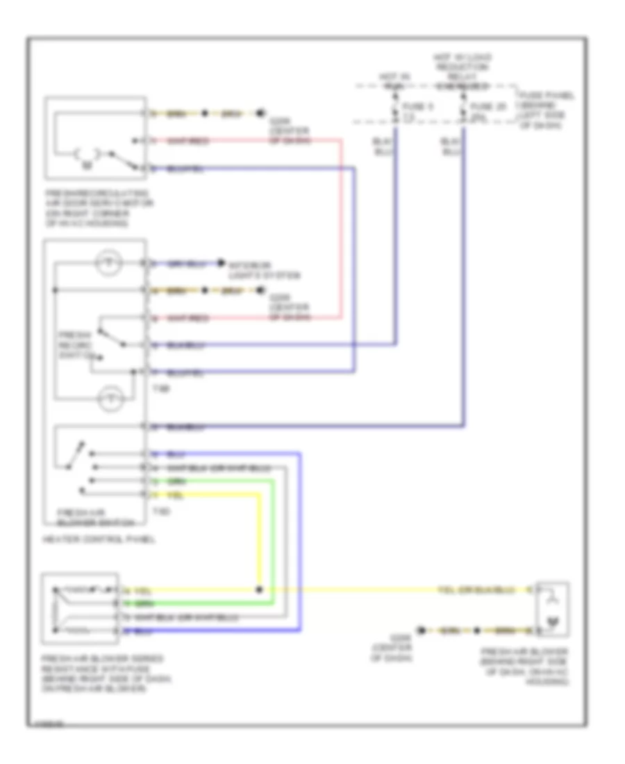
Heater Wiring Diagram for Volkswagen Jetta GL 1999
List of elements for Heater Wiring Diagram for Volkswagen Jetta GL 1999:
- Fresh air blower (behind right side of dash, on hvac housing)
- Fresh air blower series resistance with fuse (behind right side of dash, on fresh air blower)
- Fresh air blower switch
- Fresh/ recirc switch
- Fresh/recirculating air door servo motor (on right corner of hvac housing)
- Fuse 25 25a
- Fuse 5 7.5
- Fuse panel (behind left side of dash)
- G206 (center of dash)
- Heater control panel
- Hot in run
- Hot w/ load reduction relay energized
- Interior lights system
- T6d
- T8b
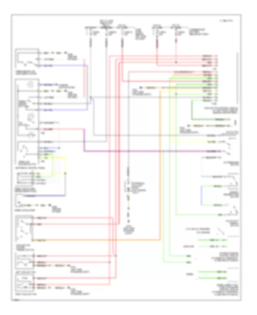
Manual A/C Wiring Diagram for Volkswagen Jetta GL 1999
List of elements for Manual A/C Wiring Diagram for Volkswagen Jetta GL 1999:
- (1.9l and 2.0l engines)
- (2.8l engine only)
- (2.8l engine)
- 1995 vftc c
- A/c clutch
- A/c cut-out thermal switch
- A/c pressure switch
- A/c switch
- After-run coolant pump (2.8l engine only)
- Ambient temperature switch
- Coolant fan control module (at left front side of engine compartment)
- Coolant fan control thermal switch
- Diesel
- Diesel direct fuel injection engine control module (at base of windshield in center of plenum)
- Fresh air blower
- Fresh air blower series resistance
- Fresh air blower switch
- Fresh/ recirc switch
- Fresh/recirc air door servo motor
- Fuse 16 10a
- Fuse 25 25a
- Fuse 3 30a
- Fuse 5 7.5a
- Fuse 8 30a
- Fuse panel (behind left side of dash)
- Fuse/bracket battery (behind battery)
- G100 (left side of engine compt)
- G206 (center of dash)
- Gasoline
- Heater-a/c control panel
- Hot at all times
- Hot in run
- Hot w/ load reduction relay energized
- Interior lights system
- Left coolant fan
- Motronic engine control module (at base of windshield, in center of plenum)
- Red
- Right coolant fan
- T10b
- T4a
- T6d
- T8b