AIR CONDITIONING
Automatic A/C Wiring Diagram (1 of 2) for Volvo S40 2004

List of elements for Automatic A/C Wiring Diagram (1 of 2) for Volvo S40 2004:
- (at left rear of engine compartment) g2
- (at left rear of engine compt) g1
- (under left side of dash, right of steering column) data link connector
- A/c evaporator & a/c outside temperature sensors (behind right side of dash)
- Anti-lock brakes system
- Climate control module (integral to a/c controls, in center of dash)
- Climate control temperature damper (behind center of dash, on left side of hvac assembly)
- Coolant temperature ecc sensor (behind upper right side of dash)
- Defogger system
- Distribution rail (behind left center of dash)
- E10
- Engine compartment fuse & relay box (at left rear corner of engine compartment)
- Fuse 10a
- Fuse 15a
- Fuse 25a
- G1 (at left rear of engine compt)
- Hot at all times
- Hot in on
- Interior lights system
- J14
- Passenger compartment fan max speed relay (behind lower right side of dash)
- Passenger compartment fan motor (under right side of dash, on hvac assembly)
- Passenger compartment fan relay
- Passenger compartment fan speed control module (behind right side of dash, on bottom of hvac assembly)
- Passenger compartment fuse & relay box (behind left side of dash)
- Pnk
- Recirculation damper motor (behind right side of dash, on bottom right of hvac assembly)
- Red
- Seats system
- Solar sensor
- Solid state
- Ventilation/floor/defroster damper motor (behind center of dash, on left side of hvac assembly)
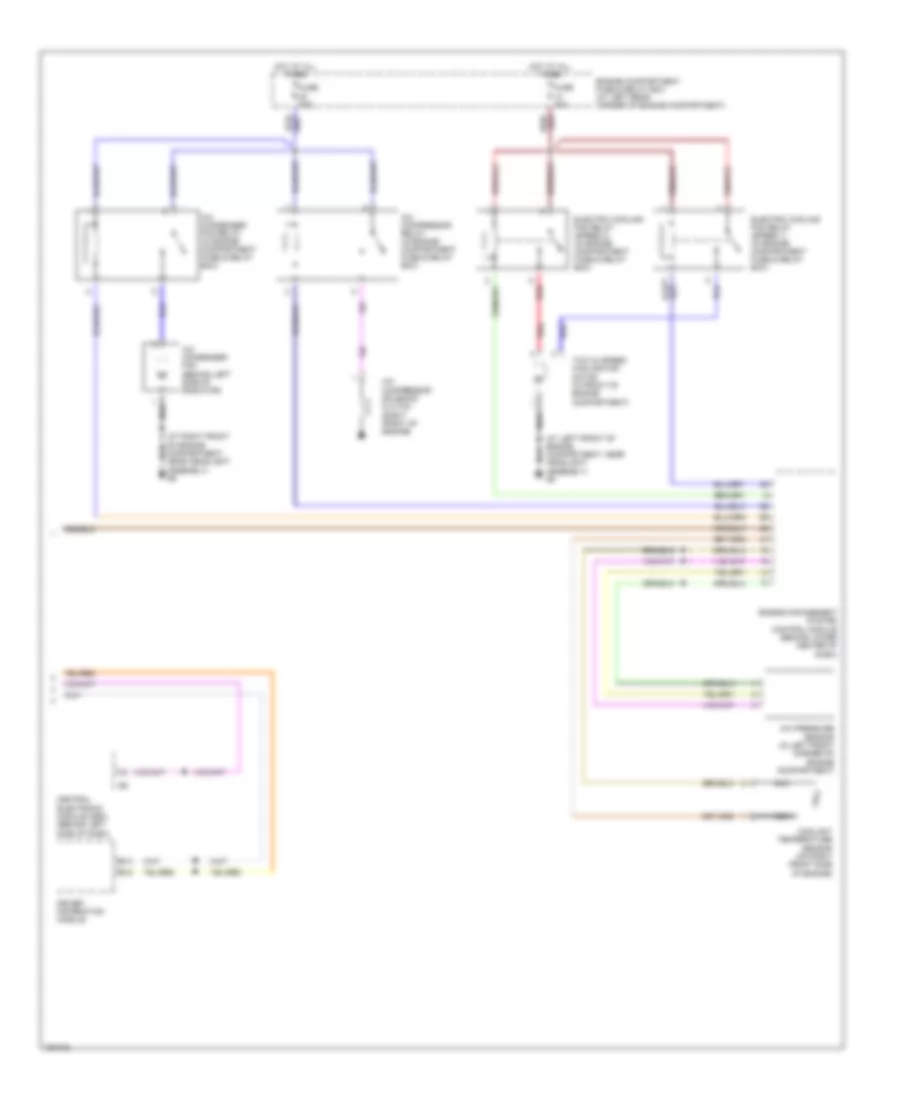
Automatic A/C Wiring Diagram (2 of 2) for Volvo S40 2004
List of elements for Automatic A/C Wiring Diagram (2 of 2) for Volvo S40 2004:
- (at left front of engine compartment, near headlight assembly) g8
- (at right front of engine compartment, near headlight assembly) g9
- A/c compressor relay (in engine compartment fuse & relay box)
- A/c compressor solenoid clutch (right front of engine)
- A/c condenser fan (behind left side of radiator)
- A/c condenser fan relay (in engine compartment fuse & relay box)
- A/c pressure sensor (in left front corner of engine compartment)
- B13
- B15
- Central electronic module (cem) (behind left side of dash)
- Coolant temperature sensor (on right front side of engine)
- Driver information module
- Electric cooling fan relay (speed 1) (in engine compartment fuse & relay box)
- Electric cooling fan relay (speed 2) (in engine compartment fuse & relay box)
- Engine compartment fuse & relay box (at left rear corner of engine compartment)
- Engine management system control module (behind lower center of dash)
- Fuse 20a
- Fuse 30a
- Hot at all times
- Nca
- Red
- Two (2) speed cooling fan motor (in front of engine compartment)